Visual system and method for synchronous positioning and mapping and mobile robot

A mobile robot and synchronous positioning technology, which is applied in the direction of control/adjustment system, instrument, non-electric variable control, etc., can solve the problems of the influence of the field of view and the inability to detect, etc., and achieve the effect of expanding the visual range and flexible installation

Pending Publication Date: 2021-12-17
深圳市丛矽微电子科技有限公司
View PDF0 Cites 0 Cited by
  • Summary
  • Abstract
  • Description
  • Claims
  • Application Information

AI Technical Summary

Problems solved by technology

Because this type of design is built-in and close to the geometric center of the body, and is a sunken structure, the fi

Method used


Image

  • Visual system and method for synchronous positioning and mapping and mobile robot
  • Visual system and method for synchronous positioning and mapping and mobile robot
  • Visual system and method for synchronous positioning and mapping and mobile robot

Examples


Embodiment Construction

[0041] In order to make the object, technical solution and advantages of the present invention clearer, the present invention will be further described in detail below in combination with specific embodiments and with reference to the accompanying drawings. It should be understood that these descriptions are exemplary only, and are not intended to limit the scope of the present invention. Also, in the following description, descriptions of well-known structures and techniques are omitted to avoid unnecessarily obscuring the concept of the present invention.

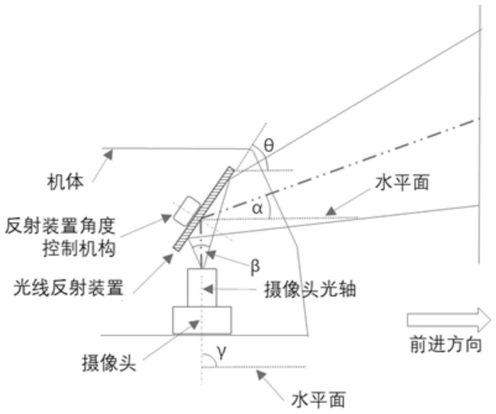
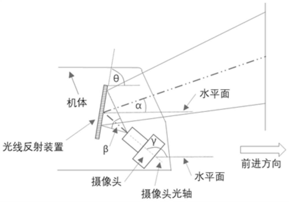
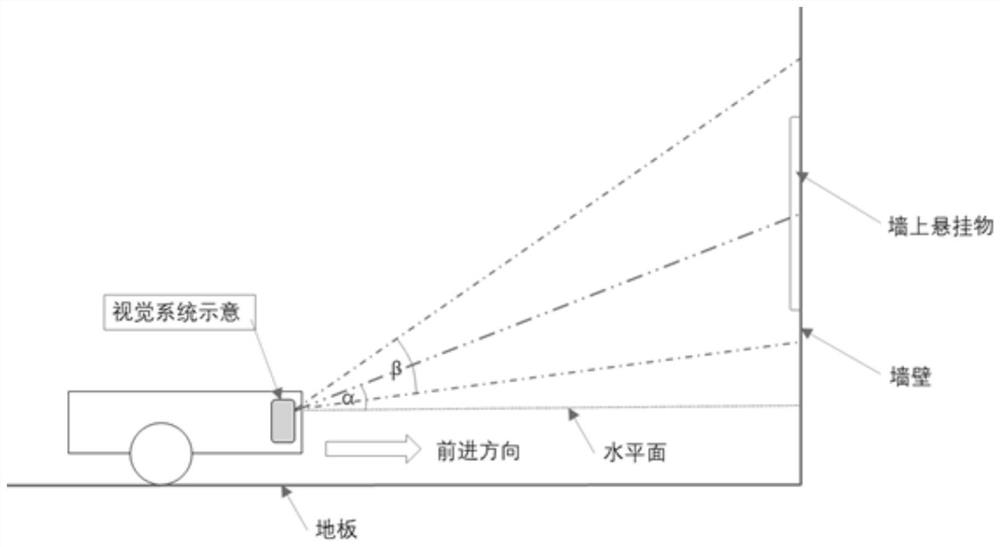
[0042] The invention provides a visual system for synchronous positioning and mapping, combining figure 1 , including a reflection device, a camera, a first control mechanism, a second control mechanism and a processor.

[0043] The camera collects visual information of the external environment through the reflection device to form an image.

[0044] The second control mechanism can adjust the angle of the camera. The ...


PUM


Abstract

The invention relates to a visual system and method for synchronous positioning and mapping and a mobile robot. The method comprises the steps of arranging a camera and a reflection device, wherein the reflection device is located above the camera, and the camera receives visual information of an external environment through the reflection device to form an image; adjusting the inclination angle of the reflection device to obtain images in different view angle ranges; and carrying out positioning or modeling based on the feature information in the image. The optical axis of the camera in the optical system does not face the advancing direction of the mobile robot, but forms an obtuse angle or a right angle with the advancing direction of the robot body relative to the top plane of the robot body. The optical system is installed at the position, which is close to a structural shell, in the mobile robot and does not protrude out of the top plane of the robot body, a sinking structure is not needed, and the installation is flexible. By adjusting the inclination angles of the camera and the reflection device, the optical system can obtain a larger view field angle, and the view field is adjustable. Binocular vision is obtained by using one camera, and binocular positioning is realized.

Description

technical field [0001] The invention relates to the technical field of machine vision, in particular to a vision system, method and mobile robot for synchronous positioning and mapping. Background technique [0002] In order to better collect effective environmental feature data, in some applications, such as sweeping robots, its simultaneous localization and mapping (SLAM) vision system will collect environmental information between 0.8 meters and 2.5 meters in the room, and extract key After characterization, as a characteristic marker of the indoor space, the auxiliary system searches and compares it, and then judges its specific location in the room to complete the path planning and navigation. [0003] In the existing sweeping robot, the vision module is a sinking structure lower than the top plane of the robot body, and is located near the geometric center of the body. The camera is placed in the sunken structure and installed obliquely. The optical axis of the camera...

Claims


Application Information

Patent Timeline
IPC IPC(8): G05D1/02
CPCG05D1/0246
Inventor 郭先清
Owner 深圳市丛矽微电子科技有限公司
Why Eureka
Try Eureka