New temperature control method

A temperature control method and controller technology, applied in the direction of using electric mode for temperature control, etc., can solve problems such as harmonic pollution of the power grid, and achieve the effects of less power grid pollution, high efficiency, and stepless temperature adjustment.

Pending Publication Date: 2021-12-17
刘浪 +1
View PDF0 Cites 0 Cited by
  • Summary
  • Abstract
  • Description
  • Claims
  • Application Information

AI Technical Summary

Problems solved by technology

[0004] In order to overcome the problem of grid harmonic pollution caused by thyristor temperature control, the present invention provides a high-frequency switch control ci

Method used


Image

  • New temperature control method
  • New temperature control method
  • New temperature control method

Examples


Embodiment 1

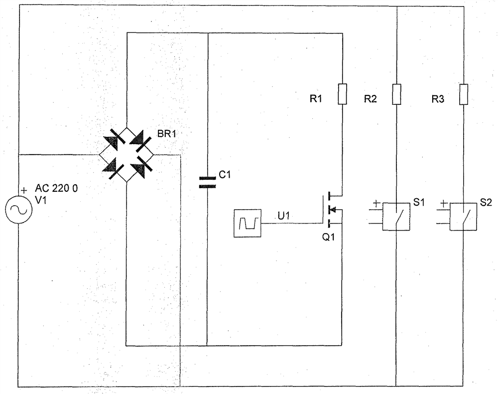
[0022] Such as figure 2 As shown, the control system is divided into a continuous control part and a stepping control part.

[0023] The continuous control part includes the bridge stack BR1. The two ends of the AC input of the bridge stack are connected to the two ends of the AC input. The position can be exchanged, Q1 is an N-channel MOSFET, its S pole is closer to the negative terminal of the steamed bun, and the PWM controller U1 controls the gate of Q1.

[0024] The segmented control part includes heating wire R2 and control switch S1, R2 and S1 are connected in series to both ends of the AC input; R3 is another heating wire, S2 is the control switch corresponding to R3, R3 and S2 are connected in series to the AC input ends.

[0025] Assuming that the overall heating power to be controlled is 2000W, you can choose R3 as a 1000W heating wire, R2 as a 500W heating wire, and R1 as a 500W heating wire.

[0026] If the output to be controlled is less than 500W, by adjusti...

Embodiment 2

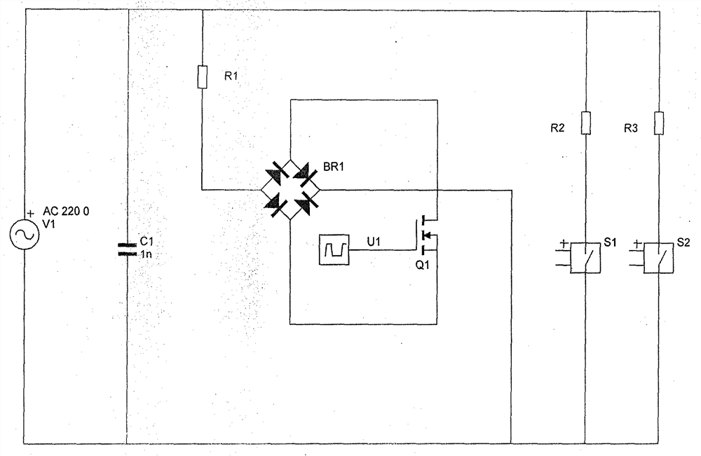
[0034] Such as image 3 As shown, the control system is divided into a continuous control part and a stepping control part.

[0035] The continuous control part includes the bridge stack BR1, the AC input end of the bridge stack is connected in series with the heating wire R1, and the rear street is at both ends of the AC input, and the control switch Q1 is connected to the positive and negative ends of the steamed wave input of BR1 after being connected in series, and Q1 is an N channel MOSFET, its S pole is closer to the negative terminal of the steamed bun, and the PWM controller U1 controls the gate of Q1.

[0036] The segmented control part includes heating wire R2 and control switch S1, R2 and S1 are connected in series to both ends of the AC input; R3 is another heating wire, S2 is the control switch corresponding to R3, R3 and S2 are connected in series to the AC input ends.

[0037] Compared with Embodiment 1, the circuit position of the heating wire R1 has been adj...


PUM


Abstract

The invention discloses a temperature control method, which adopts a mode of combining step control and continuous control for temperature control, so as to realize a function of continuously adjusting temperature in a full power range. The continuous control part comprises a diode bridge rectifier, a filter capacitor, a heating wire and an MOSFET; and the step control comprises a series of heating wires and corresponding control switches (such as relays), wherein the heating wires and the corresponding control switches are connected in series and then are directly connected to an alternating current input power supply. According to the continuous control part, high-frequency pulse width modulation control is adopted for driving signals of the MOSFET, and switching modulation is carried out by adjusting the duty ratio of pulses so as to achieve the purpose of continuously adjusting the power. When the required power exceeds the continuously adjustable part, the step cascade part is synchronously connected in a grid to participate in the adjustment process in a larger power range, and the continuous part and the grading part are matched to work to realize high-power constant temperature control.

Description

technical field [0001] The invention relates to a temperature control method, in particular to a continuously adjustable temperature control method. Background technique [0002] Now the common constant temperature control is to use bidirectional thyristor. The circuit shown in the figure below is another bidirectional thyristor temperature control circuit. figure 1 The middle RL is the electric furnace wire, which is connected in series with the thyristor V, and VD1, VD2 and RP form the trigger circuit. Adjusting RP can change the conduction angle of V, so that the effective value of the voltage at both ends of the heating wire R1 can be changed steplessly within 0-220V, so the purpose of controlling the furnace temperature can be achieved. [0003] However, the use of thyristors to control temperature will generate high-order harmonics, which will distort the grid voltage waveform and seriously interfere with the grid. Contents of the invention [0004] In order to ov...

Claims


Application Information

Patent Timeline
IPC IPC(8): G05D23/19
CPCG05D23/19
Inventor 刘浪张军峰
Owner 刘浪
Why Eureka
Try Eureka