[0025] The advantages of the present invention are further described below with reference to the accompanying drawings and specific embodiments.
[0026] Exemplary embodiments will be described in detail herein, examples of which are illustrated in the accompanying drawings. When the following description refers to the drawings, the same numbers in different drawings refer to the same or similar elements unless otherwise indicated. The implementations described in the illustrative examples below are not intended to represent all implementations consistent with this disclosure. Rather, they are merely examples of apparatus and methods consistent with some aspects of the present disclosure, as recited in the appended claims.
[0027] The terminology used in the present disclosure is for the purpose of describing particular embodiments only and is not intended to limit the present disclosure. As used in this disclosure and the appended claims, the singular forms "a," "the," and "the" are intended to include the plural forms as well, unless the context clearly dictates otherwise. It will also be understood that the term "and/or" as used herein refers to and includes any and all possible combinations of one or more of the associated listed items.
[0028] It should be understood that although the terms first, second, third, etc. may be used in this disclosure to describe various pieces of information, such information should not be limited by these terms. These terms are only used to distinguish the same type of information from each other. For example, first information may also be referred to as second information, and similarly, second information may also be referred to as first information, without departing from the scope of the present disclosure. The word "if" as used herein can be interpreted as "at the time of" or "when" or "in response to determining," depending on the context.
[0029] In the description of the present invention, it should be understood that the terms "portrait", "horizontal", "upper", "lower", "front", "rear", "left", "right", "vertical", The orientation or positional relationship indicated by "horizontal", "top", "bottom", "inside", "outside", etc. is based on the orientation or positional relationship shown in the drawings, and is only for the convenience of describing the present invention and simplifying the description, rather than An indication or implication that the referred device or element must have a particular orientation, be constructed and operate in a particular orientation, is not to be construed as a limitation of the invention.
[0030] In the description of the present invention, unless otherwise specified and limited, it should be noted that the terms "installed", "connected" and "connected" should be understood in a broad sense, for example, it may be a mechanical connection or an electrical connection, or two The internal communication between the elements may be directly connected or indirectly connected through an intermediate medium. For those of ordinary skill in the art, the specific meanings of the above terms can be understood according to specific situations.
[0031] In the ensuing description, suffixes such as 'module', 'component' or 'unit' used to represent elements are used only to facilitate the description of the present invention, and have no specific meaning per se. Therefore, "module" and "component" can be used interchangeably.
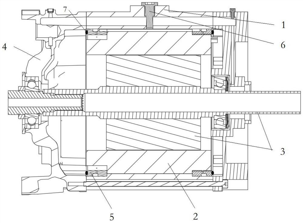
[0032] The invention discloses an oil-cooled electric drive system for testing, which is used for testing the conduction effect of oil circuits in various aspects of an oil-cooled electric drive axle, comprising a casing 1 and a cylinder arranged in the casing 1 The stator 2 is shaped like a stator and the rotor 3 is arranged in the center of the stator 2 . The structure of the main functional stator 2 and rotor 3 of this oil-cooled electric drive axle is usually the same as the structure of the application-type oil-cooled electric drive axle, but other auxiliary structures, such as the housing 1, need to be designed to be transparent to avoid During the test process, the conduction of the oil passages of the stator 2 and the rotor 3 and the oil rejection of the rotor 3 can be observed accurately and intuitively. In the present invention, the casing 1 is designed as a transparent acrylic material, which is easy to observe, simple to process, and more convenient to use than ordinary glass.
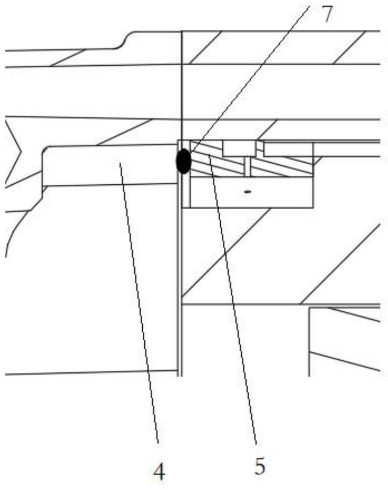
[0033]However, due to the limited processing accuracy of acrylic material, and the oil ring 5 usually adopts a 3D printing structure, the accuracy is also poor, so that the end cover 4 of the housing 1 and other structures (such as oil rings) are either press fit or clearance. There is a tolerance in the fit, and the clearance fit may lead to the leakage of the cooling oil in the stator 2 and the rotor 3, which is not allowed, so we use a press fit. In addition, due to the limited strength of the acrylic material, when the press fit is used, the shell 1 has a rigid connection force and is damaged. Therefore, the present invention adopts the elastic member 7 in the connection between the shell 1 and other structures, so that the shell 1 and the other structure are connected. The cooperation of other structures is elastic press fit, which can not only ensure its tightness and prevent leakage, but also ensure the integrity of the acrylic shell with poor strength and prevent it from being damaged due to rigid connection.
[0034] For details, see the appendix Figure 1-4 , the housing 1 includes an end cover 4, the end face of the stator 2 is detachably connected with an oil ring 5, the outer side of the oil ring 5 is provided with an end cover 4, and the end cover 4 is fixedly connected with the oil ring 5. The side of the oil ring 5 facing the end cover 4 is provided with a first abutment block 8 , and the side of the end cover 4 facing the oil ring 5 is provided with a second abutment block 11 at a position corresponding to the first abutment block 8 . The cover 4 is connected in contact with each other through the first butt block 8 and the second butt block 11, which is a rigid connection. In the present invention, the first butt block 8 and the second butt The second abutting block 11 is also provided with an elastic member 7 , so that the end cover 4 is provided between the end cover 4 and the oil ring 5 in an elastic press fit.
[0035] Usually, we use only one of the first abutting block 8 and the second abutting block 11 to provide the elastic member 7, because the first abutting block 8 and the second abutting block 11 are provided with the elastic member 7 at the same time. There is a misalignment of the connections between each other and the connection is not tight.
[0036] The elastic member 7 is usually set by means of dispensing, and the elastic member 7 can be selected from elastic materials such as rubber.
[0037] When observing the oil conduction of the oil circuit, since the stator 2 is located outside the rotor 3, it is covered. When the oil circuit of the stator 2 is turned on, the oil ring will spray oil to the windings of the stator 2, thereby affecting the oil rejection phenomenon of the rotor 3. Therefore, when verifying the oil rejection effect of the rotor 3, the oil passage of the stator 2 needs to be cut off, so that the oil rejection phenomenon of the rotor 3 can be observed more accurately.
[0038] For details, see the appendix Figure 5-7 , the casing 1 is provided with an axial first oil guide oil circuit, the stator 2 is provided with an axial second oil guide oil circuit, and the cooling oil enters through the first oil guide oil circuit and the second oil guide oil circuit in turn. Windings at both ends of the stator 2 to cool it.
[0039] In the present invention, an oil plug 6 is provided on the housing 1, and the oil plug 6 is radially inserted into the first oil guide oil passage and connected with the second oil guide oil passage to block the second oil guide oil passage, so that the first oil guide oil passage is blocked. The cooling oil in the first oil-conducting oil passage cannot enter the windings at both ends of the stator 2 through the second oil-conducting oil passage, thereby blocking the oil-conducting oil passage of the stator 2 . The oil plug 6 is provided with a rubber pad on the side in contact with the second oil guide oil passage to ensure its sealing performance to the second oil guide oil passage.
[0040] When it is necessary to conduct the oil passage of the stator 2, the oil plug 6 is radially fixed on the outer side of the first oil guide oil passage to connect the first oil guide oil passage and the second oil guide oil passage, so that the first oil guide oil passage The cooling oil inside enters the windings at both ends of the stator 2 through the second oil guide oil passage.
[0041] Preferably, the rotor 3 is arranged on the housing 1 through a bearing. It also includes a third oil guide oil circuit. One end of the third oil guide oil circuit is connected with the first oil guide oil circuit, and the other end is connected with the bearing. The cooling oil in the first oil guide oil circuit can flow to the bearing to lubricate the bearing. and cooling to ensure its working state. The radial dimension of the oil plug 6 of the present invention is smaller than that of the first oil guide oil passage, so that even if the oil plug 6 is radially inserted into the first oil guide oil passage and connected to the second oil guide oil passage, the The cooling oil in the first oil guide oil passage can still flow to the bearing, and it will not cut off the oil passage of the rear bearing, ensuring that the rear bearing will not be damaged.
[0042] Preferably, the oil plug 6 includes two types of the first oil plug 6 and the second oil plug 6, and the axial length of the first oil plug 6 is greater than that of the second oil plug 6. Insert the longer first oil plug 6 radially into the first oil guide oil passage to connect its end with the second oil guide oil passage, so that the cooling oil in the first oil guide oil passage cannot pass through the second oil guide oil passage. The oil guide oil circuit enters the second oil guide path to realize the isolation of the stator 2 oil circuit. The shorter second oil plug 6 is radially fixed on the outside of the first oil guide oil path to release the first oil guide oil path and the second oil guide oil path, so that the cooling oil in the first oil guide oil path The second oil guide oil path enters the second oil guide path to realize the release of the stator 2 oil path. In this embodiment, by selecting and installing two different oil plugs 6, the isolation and circulation of the oil circuit of the stator 2 can be realized, the operation is simple, and the effect is obvious.
[0043] Preferably, in another preferred embodiment of the oil plug 6, the oil plug 6 is a telescopic piece. The oil plug 6 is extended and radially inserted into the first oil guide oil passage and connected with the second oil guide oil passage, so that the cooling oil in the first oil guide oil passage cannot enter the second oil guide oil passage through the second oil guide oil passage or the oil plug 6 is shortened and fixed on the outside of the first oil guiding oil passage, so that the cooling oil in the first oil guiding oil passage enters the second oil guiding passage through the second oil guiding oil passage. In this embodiment, only one oil plug 6 needs to be installed, and the isolation and circulation of the oil circuit of the stator 2 can be realized by adjusting it telescopically.
[0044] Further, the telescopic oil plug 6 includes an axially penetrating fixed part and a telescopic part arranged inside the fixed part. The oil passage is connected, and the telescopic part is contracted into the fixed part so that the fixed part is radially fixed on the outer side of the first oil guide oil passage. The connection between the telescopic part and the fixed part is usually threaded, so as to realize the adjustment of the position of the telescopic part relative to the fixed part.
[0045] Preferably, whether it is the telescopic oil plug 6 or the long and short oil plugs 6 of different models, in a preferred embodiment, the outer surface of the oil plug 6 is provided with threads, and the oil plug 6 is connected to the housing 1 through the threads. If it is a long or short oil plug 6, it can be installed on the housing 1 directly through the knob of the long and short oil plug 6. In the case of the telescopic oil plug 6, the screw is provided on the fixed part, the fixed part is fixedly connected with the housing 1, and the vertical positional relationship between the telescopic part and the fixed part can be directly adjusted subsequently.
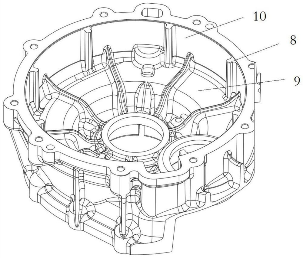
[0046] Preferably, in order to ensure the stability of the connection between the end cover 4 and the oil ring 5, the number of the first abutting block 8 and the second abutting block 11 should be an even number, and they are symmetrical on the oil ring 5 and the end cover 4, respectively. It is set so that the connecting force can be evenly distributed on the oil ring 5 and the end cover 4 . e.g. attached Figure 3-4 8 shown.
[0047] Preferably, the number of the first docking blocks 8 and the second docking blocks 11 may not be an even number, but should be greater than or equal to two, and they are evenly arranged on the oil ring 5 and the end cover 4 to ensure the connection. The force is evenly distributed on the oil ring 5 and the end cover 4. For example three.
[0048] The end cover 4 includes a left end cover and a right end cover, and the left and right ends of the stator iron core are respectively provided with a left oil ring and a right oil ring.
[0049] Specifically, two or more first abutting blocks 8 are provided inside the left end cover facing the left oil ring, and each left oil ring is provided with a corresponding number of second abutting blocks 11 facing the left end cover. An elastic member 7 is provided between the second abutting blocks 11 , and the elastic member 7 is used for elastic pressing fit.
[0050] There are two or more right end cover flanges facing the right oil ring inside the right end cover, each right oil ring facing the right end cover is provided with a corresponding number of second docking blocks 11, the first docking block 8 and the second docking block An elastic member 7 is arranged between 11, through which the elastic member 7 is elastically press-fitted.
[0051] The free height of the elastic piece 7 is greater than the gap between the first abutment block 8 and the second abutment block 11. During assembly, the first abutment block 8 of the left end cover presses the left oil ring against the left side of the stator core through the elastic piece 7. On the right side, the first abutment block 8 of the right end cover presses the right oil ring on the right side of the stator core through the elastic piece 7 .
[0052] The rotating shaft of the rotor 3 is arranged on the right end cover through a bearing, and an oil seal is arranged between the right end cover and the rotor shaft, and the dynamic sealing between the rotating shaft of the rotor 3 and the right end cover is realized by the oil seal.
[0053] better, see appendix Figure 3-4 , the oil ring 5 includes a first cover 9 and a first connecting edge 10 of the outer ring of the first cover 9. The first connecting edge 10 axially protrudes from the first cover 9, and the first abutting block is arranged on the first cover 9, And it is connected with the first connecting edge 10. Through this design, the connecting force is not only borne by the first cover 9, but simultaneously borne by the first cover 9 and the first connecting edge 10, so that the structural strength of the oil ring 5 is more stable.
[0054] The end cover 4 is also provided with a second cover 12 and a second connecting edge 13 of the outer ring of the second cover 12. The second connecting edge 13 protrudes axially from the second cover 12, and the second docking block is arranged on the second cover. 12 and is connected with the first connecting edge 10, through this design, the connecting force is not only borne by the second cover 12, but is borne by the second cover 12 and the second connecting edge 13 at the same time, so that the strength of the end cap structure is stronger. Stablize.
[0055] Preferably, the end cover is provided with a central hole through which the rotating shaft of the rotor 3 passes, and the second abutting block is also connected with the central hole, thereby connecting the center and outside of the end cover 4, making the connection more stable.
[0056] In addition, due to the use of the structure of the present invention, the electric drive system for testing replaces the oil plug 6 with a short oil plug 6 after the test, or makes the telescopic length of the telescopic oil plug 6 expand and contract inside the fixed part, so that the stator 2 When the oil circuit flows, it can be used as an application-type electric drive axle.
[0057] It should be noted that the embodiments of the present invention have better practicability, and do not limit the present invention in any form, and any person skilled in the art may use the technical contents disclosed above to change or modify into equivalent effective embodiments However, any modifications or equivalent changes and modifications made to the above embodiments according to the technical essence of the present invention without departing from the content of the technical solution of the present invention still fall within the scope of the technical solution of the present invention.