Heat sensation adjustment device
An adjustment device and warming technology, applied in transportation and packaging, heating/cooling equipment, vehicle parts, etc., can solve the problems of occupant's mental state and occupant's physical state, etc.
- Summary
- Abstract
- Description
- Claims
- Application Information
AI Technical Summary
Problems solved by technology
Method used
Image

Examples
no. 1 approach
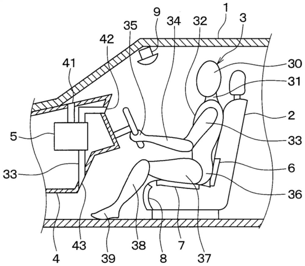
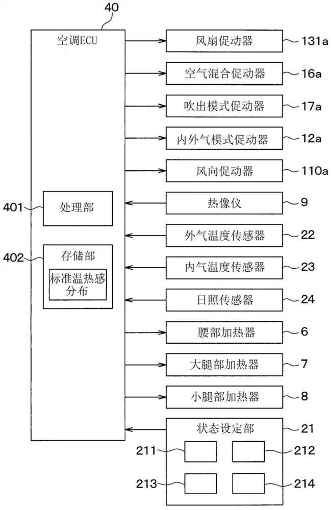
[0038] Hereinafter, the first embodiment will be described. The temperature adjustment device of this embodiment is figure 1 In the vehicle interior of the vehicle 1 shown, the warmth feeling of the occupant 3 seated in the driver's seat 2 is adjusted. The thermal adjustment device includes an air conditioning unit 5 arranged inside the damper 4 , a waist heater 6 , a thigh heater 7 , a calf heater 8 , and a thermal imager 9 mounted on the driver's seat 2 . Hereinafter, up, down, left, and right refer to up, down, left, and right in a vehicle.
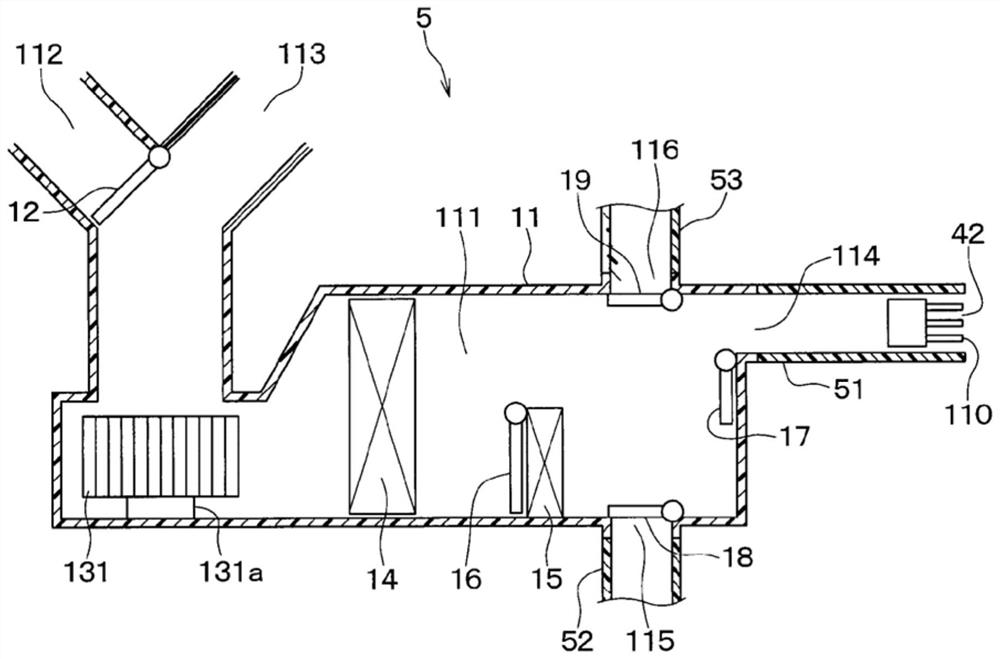
[0039] The air conditioning unit 5 blows air whose temperature has been adjusted into the vehicle interior from defroster outlets 41 , face outlets 42 , and foot outlets 43 attached to the surface of the apron 4 .
[0040] The lumbar heater 6 is an electric heater provided on the front surface side of the seat back below the vertical center portion of the seat back of the driver's seat 2 . The waist heater 6 mainly heats the waist 3...
no. 2 approach
[0107] Next, a second embodiment will be described. Such as Figure 11 As shown, in this embodiment, a display device 60 and a touch panel 61 are added to the structure of the first embodiment.
[0108] The display device 60 is a device that allows an occupant of the vehicle to see an image. The display device 60 may be mounted on the instrument panel or fender of the vehicle, or may be mounted on the steering wheel. Alternatively, the display device 60 may also be a head-up display that utilizes the reflection of light in the windshield of the vehicle to make the occupant see an image as a virtual image in front of the windshield.
[0109] Alternatively, the display device 60 may be a terminal carried by an occupant of the vehicle. In this case, the air conditioner ECU 40 controls the display content of the display device 60 by performing wireless communication with the display device 60 .
[0110] The touch panel 61 is an operation device for the occupant to operate acco...
no. 3 approach
[0195] Next, a third embodiment will be described. Compared with the second embodiment, the air conditioner ECU 40 of this embodiment executes Figure 23 shown in the processing instead of Figure 17 processing. Others are the same as the second embodiment.
[0196] exist Figure 17 processing and Figure 23 In the processing, the same step number is attached to the step with the same processing content. Figure 23 processing in Figure 17 Step S210 is added to the processing of . Hereinafter, the difference from the second embodiment will be mainly described, and the description of the same parts as the second embodiment will be omitted.
[0197] exist Figure 23 In the processing of , the air conditioner ECU 40 executes step S210 following step S205, and executes step S215 following step S210. In step S210 , the air conditioner ECU 40 calculates the required time to reach the target for the body part targeted for each body part control. The time required to reach t...
PUM
 Abstract
Description
Claims
Application Information
 - R&D Engineer
- R&D Manager
- IP Professional
- Industry Leading Data Capabilities
- Powerful AI technology
- Patent DNA Extraction
Browse by: Latest US Patents, China's latest patents, Technical Efficacy Thesaurus, Application Domain, Technology Topic.
© 2024 PatSnap. All rights reserved.Legal|Privacy policy|Modern Slavery Act Transparency Statement|Sitemap