Supercharge Your Innovation With Domain-Expert AI Agents!

Thyristor circuit and thyristor protection method

A thyristor, thyristor control technology, applied in the direction of thyristors, circuits, electrical components, etc., can solve the problems of thyristor blocking ability deterioration, thyristor failure, thermal damage, etc.

Pending Publication Date: 2021-12-17
ABB (SCHWEIZ) AG
View PDF10 Cites 0 Cited by
  • Summary
  • Abstract
  • Description
  • Claims
  • Application Information

AI Technical Summary

Problems solved by technology

As the temperature of the junction, or junction temperature, rises to high values, the blocking ability of the thyristor begins to deteriorate, resulting in a high resistance circuit through the junction
Therefore, in the case of blocking state and fault current conditions, an increase in junction temperature may also be promoted, which may lead to failure or thermal destruction of the thyristor

Method used


Image

  • Thyristor circuit and thyristor protection method
  • Thyristor circuit and thyristor protection method
  • Thyristor circuit and thyristor protection method

Examples


Embodiment Construction

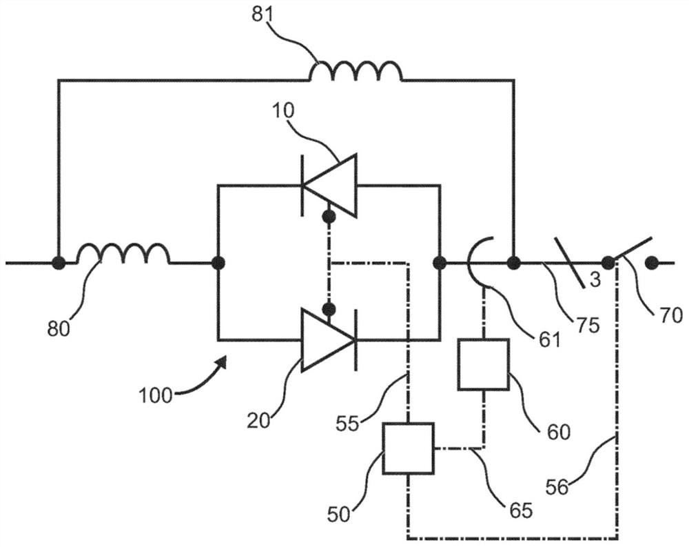
[0036] figure 1 A thyristor circuit 100 is shown having a branch circuit comprising a series circuit consisting of a snubber reactor 80 and a pair of thyristors 10 , 20 connected in antiparallel. The shunt reactor 81 is connected to the series circuit in electrical parallel. exist figure 1 In , upstream of the feeder 75, the numeral "3" indicates a three-phase system in which a thyristor circuit 100 is provided in each of the three branches. However, the present disclosure is not limited to three-phase systems, and 1, 2 or 4 or more branches may also be provided. A three-phase circuit breaker 70 is provided to electrically interrupt the feeder 75 upon receipt of a circuit breaker interruption signal.

[0037] The thyristor control circuit 50 is configured such that it can selectively trigger the thyristors 10 , 20 . Selective triggering as used herein may comprise a thyristor control circuit 50 which controls each thyristor 10 , 20 independently of each other. As used her...


PUM


Abstract

A thyristor circuit (100) comprises at least one branch comprising at least one thyristor (10, 20), a thyristor control circuit (50) and a current detector (60, 61). The current detector (60, 61) is configured to detect a current value representative of an electrical current flowing through the thyristor and to input the detected current value into the thyristor control circuit. The thyristor control circuit is configured to determine a fault condition in which the detected current value exceeds a predetermined current threshold based on a deteriorated blocking ability of the thyristor. Dependent on the determination result, the thyristor control circuit triggers the thyristor into a conductive state.

Description

technical field [0001] The invention relates to a thyristor circuit having at least one branch comprising at least one thyristor and a thyristor protection method for protecting a thyristor in at least one branch. Background technique [0002] In high voltage and high current applications, electronic devices often use thyristors as power electronic components. Upon receiving a trigger current at its gate, the thyristor begins conducting current in a path from its anode terminal through its semiconductor junction stack to its cathode terminal. In the literature, triggering is also called excitation or gating. Thyristors are non-conducting, or blocking, unless triggered. [0003] Therefore, thyristors are used for current control in various applications, for example, as crowbars, high power rectifiers, etc. When thyristors or stacks of multiple series thyristors are connected in anti-parallel, they can be used to control current flow in both directions, eg in AC application...

Claims


Application Information

Patent Timeline
Patent Type & Authority Applications(China)
IPC IPC(8): H03K17/14H03K17/082H03K17/08H01L27/02
CPCH01L27/0248H03K17/0824H03K2017/0806H03K17/14
Inventor 雷托·斯塔德勒拉尔夫·贝奇勒
Owner ABB (SCHWEIZ) AG
Features
  • R&D
  • Intellectual Property
  • Life Sciences
  • Materials
  • Tech Scout
  • Unparalleled Data Quality
  • Higher Quality Content
  • 60% Fewer Hallucinations
Learn More