Tail gas treatment device for ultra-low-nitrogen fuel gas module evaporator
A technology of tail gas treatment and evaporator, which is applied in the direction of combination device, use of liquid separation agent, chemical instruments and methods, etc., can solve the problems of no tail gas treatment efficiency, ineffective use of gas, etc., and achieve the effect of saving resources
- Summary
- Abstract
- Description
- Claims
- Application Information
AI Technical Summary
Problems solved by technology
Method used
Image
Examples
Embodiment 1
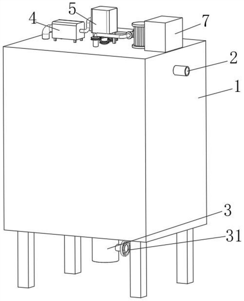
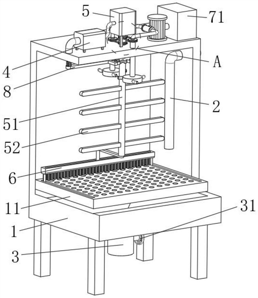
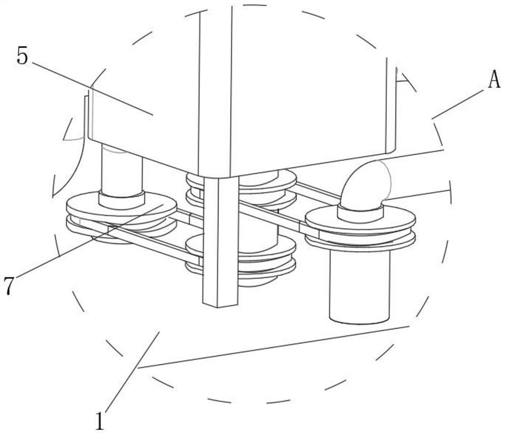
[0031] refer to Figure 1-6 , a tail gas treatment device for an ultra-low nitrogen gas module evaporator, comprising a treatment box 1, a filter screen 11 is fixedly installed on the inner wall of the treatment box 1, and the sediment produced by the tail gas treatment is filtered, and two groups are arranged on the upper surface of the filter screen 11 Chute 12, the inside of processing box 1 is communicated with intake pipe 2, and intake pipe 2 is inserted into the inside of processing box 1, to facilitate the tail gas to enter the inside of processing box 1, and the bottom surface of processing box 1 is connected with drain pipe 3, for use The exhausted liquid is discharged. A valve 31 is arranged inside the discharge pipe 3 to control the opening and closing of the discharge pipe 3. A compressor 4 is fixedly installed on the upper surface of the treatment box 1 to absorb and compress the processed gas. The air outlet of machine 4 is communicated with air motor 5, and air ...
Embodiment 2
[0036] Such as Figure 1-6 As shown, this embodiment is basically the same as Embodiment 1. Preferably, the reciprocating assembly 8 includes a half gear 81 sleeved on the outer surface of the stirring shaft 51, and the outer surface of the half gear 81 is meshed with a rack 82. The outer surface is fixedly connected with a cleaning brush 2 83, and the upper surface of the cleaning brush 83 is fixedly equipped with a connecting rod 84, and the upper end of the connecting rod 84 is rotatably connected with the inner top surface of the processing box 1, and the outer surface of the connecting rod 84 is covered with Spring 85, and one end of spring 85 is fixedly connected with the upper surface of cleaning brush 2 83, and the other end of spring 85 is fixedly connected with the inner top surface of processing box 1.
[0037] In this embodiment, during the rotation of the connecting rod 65, the half gear 81 sleeved on the outer surface of the stirring shaft 51 will also start to r...
Embodiment 3
[0039] Such as Figure 1-6 As shown, this embodiment is basically the same as Embodiment 1. Preferably, the air inlet of the compressor 4 communicates with the processing box 1 through a gas pipe, and an adsorption net is provided at the communication port.
[0040] In this embodiment, the compressor 4 is connected to the treatment box 1 through a gas pipe, so that the treated tail gas can be absorbed and utilized by the compressor 4, saving certain resources.
PUM
 Abstract
Description
Claims
Application Information
 - R&D
- Intellectual Property
- Life Sciences
- Materials
- Tech Scout
- Unparalleled Data Quality
- Higher Quality Content
- 60% Fewer Hallucinations
Browse by: Latest US Patents, China's latest patents, Technical Efficacy Thesaurus, Application Domain, Technology Topic, Popular Technical Reports.
© 2025 PatSnap. All rights reserved.Legal|Privacy policy|Modern Slavery Act Transparency Statement|Sitemap|About US| Contact US: help@patsnap.com


