Supercharge Your Innovation With Domain-Expert AI Agents!

Fixing clamp, assembling component and assembling method

A technology for fixing fixtures and clamping rings, which is applied to workpiece clamping devices, hand-held tools, manufacturing tools, etc., and can solve problems such as the inability to check the A3 gap of the fitting surface with a feeler gauge, and the inability to judge the installation of the low-pressure turbine shaft 20 in place, etc.

Active Publication Date: 2021-12-21
AECC COMML AIRCRAFT ENGINE CO LTD
View PDF5 Cites 1 Cited by
  • Summary
  • Abstract
  • Description
  • Claims
  • Application Information

AI Technical Summary

Problems solved by technology

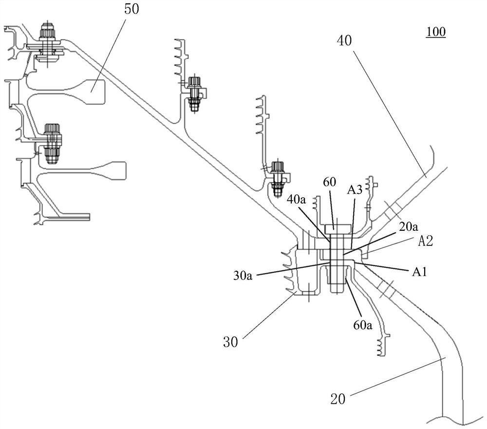
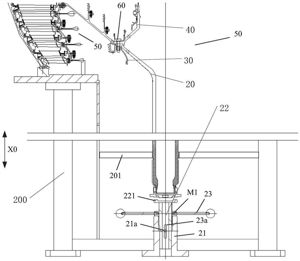
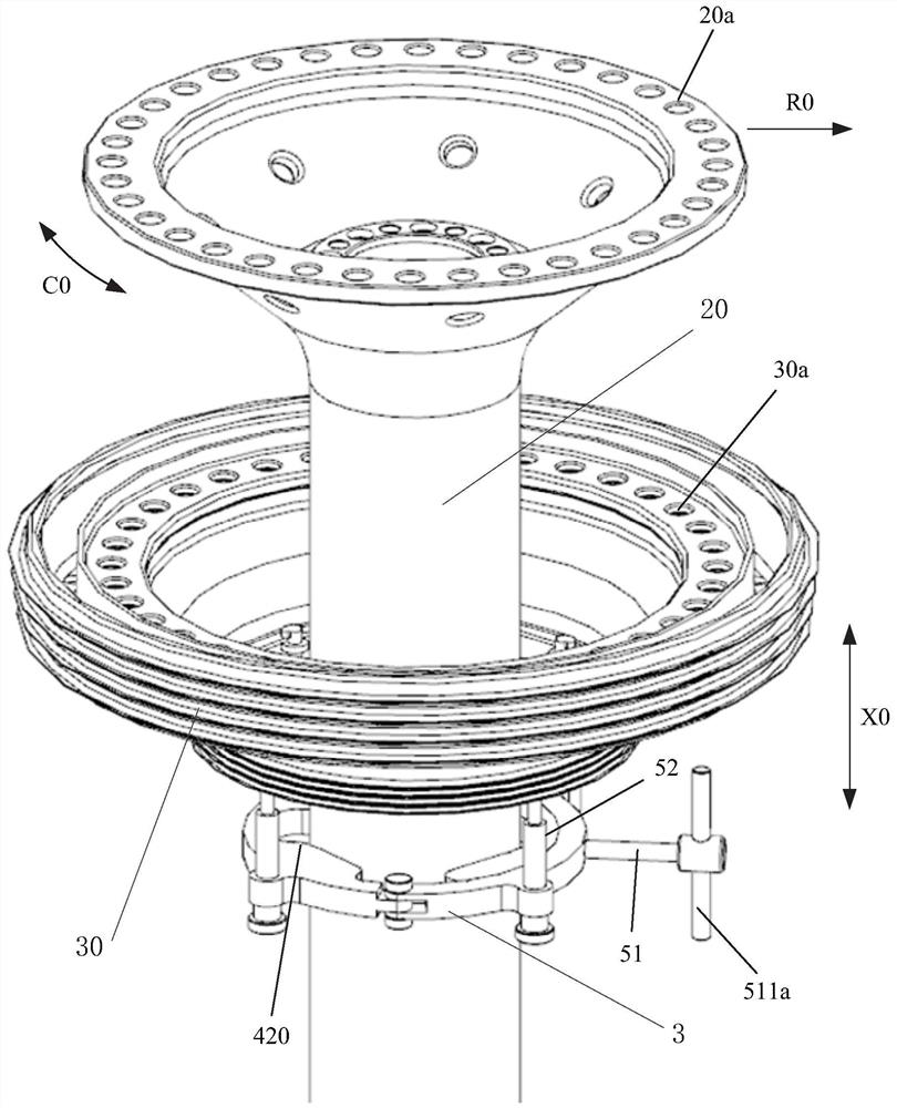
However, the sealing ring 30 is an outsourcing structure. After being installed on the low-pressure turbine shaft 20, the connection surface or the fitting surface A3 between the low-pressure turbine shaft 30 and the supporting cone wall 40 is completely blocked, and the fitting surface A3 cannot be checked by a feeler gauge. Therefore, it is impossible to judge whether the low-pressure turbine shaft 20 is installed in place

Method used


Image

  • Fixing clamp, assembling component and assembling method
  • Fixing clamp, assembling component and assembling method
  • Fixing clamp, assembling component and assembling method

Examples


Embodiment Construction

[0026] The present invention will be further described below in conjunction with specific embodiments and accompanying drawings. In the following description, more details are set forth in order to fully understand the present invention, but the present invention can obviously be implemented in a variety of other ways different from this description, Those skilled in the art can make similar promotions and deductions based on actual application situations without violating the connotation of the present invention, so the content of this specific implementation manner should not limit the protection scope of the present invention.

[0027] For example, the description that the first feature described later in the specification is formed on or above the second feature may include the embodiment in which the first feature and the second feature are formed through direct contact, and may also include an embodiment in which the first feature and the second feature are formed. Embodi...


PUM


Abstract

The invention provides a fixing clamp used for assisting in mounting a sealing ring onto a low-pressure turbine shaft. The first ends of a first half ring and a second half ring of a clamping ring are pivoted with each other, and the second ends of the first half ring and the half ring are detachably connected; in a clamping and ejection mechanism, an ejection rod penetrates through the first half ring and is in threaded connection with the first half ring, the first end of the ejection rod is located on the outer side of the clamping ring, the second end of the ejection rod is located on the inner side of the clamping ring, an ejection block is located on the inner side of the clamping ring, the ejection rod is rotatably connected with the ejection block, and the ejection block is used for cooperating with the second half ring so as to clamp the low-pressure turbine shaft. at least three clamping jaws are distributed in the circumferential direction, and in each clamping jaw, an adjusting rod is rotatably supported on the clamping ring; and two flanges in each clamping jaw protrude from the side direction of the corresponding adjusting rod, and at least one flange away from the clamping ring is in a non-whole-circle shape. The invention further provides an assembling component comprising the fixing clamp and an assembling method adopting the assembling component. Through the adoption of the fixing clamp and the assembling component, the assembling method can be conveniently executed, and the attaching face of the low-pressure turbine shaft and a supporting cone wall can be conveniently checked when a low-pressure turbine unit body is assembled.

Description

technical field [0001] The present invention relates to a method for assembling a low-pressure turbine unit body, in particular, to an assembly assembly for assembling a low-pressure turbine unit body, and more particularly, to a fixing method for an auxiliary seal ring mounted to a low-pressure turbine shaft fixture. Background technique [0002] The low-pressure turbine unit body of the engine is usually divided into two parts: the low-pressure turbine rotor and the shaft. The low-pressure turbine shaft and the supporting cone wall of the low-pressure turbine rotor adopt a short spigot interference fit with an interference of 0.15-0.2, and then are connected by bolts. Due to the high tightness of the seam fit, it is necessary to check whether the two fit together during the installation process. In the conventional assembly process, use a 0.03 feeler gauge to check the gap between the mating surfaces, and if it fails to pass, it is considered that the mating surfaces of t...

Claims


Application Information

Patent Timeline
Patent Type & Authority Applications(China)
IPC IPC(8): B25B11/02B25B27/00
CPCB25B11/02B25B27/00Y02E10/20
Inventor 郑思凯胡一廷朱亮涂卫强
Owner AECC COMML AIRCRAFT ENGINE CO LTD
Features
  • R&D
  • Intellectual Property
  • Life Sciences
  • Materials
  • Tech Scout
  • Unparalleled Data Quality
  • Higher Quality Content
  • 60% Fewer Hallucinations
Learn More