Quantitative wood cutting device

A cutting device and a technology for wood, applied in the field of wood processing, can solve the problems of inclination of the cut surface, cumbersome process, unfavorable practical use, etc., and achieve the effect of facilitating batch cutting operations

Pending Publication Date: 2021-12-21
长兴嘉年华家居有限公司
View PDF0 Cites 0 Cited by
  • Summary
  • Abstract
  • Description
  • Claims
  • Application Information

AI Technical Summary

Problems solved by technology

[0003] In the preliminary processing of wood, it is necessary to carry out quantitative cutting of wood. During quantitative cutting, the tools used by workers are different according to the actual situation. The actual structure of this type of cutting table is relatively simple. Generally, workers temporarily assemble it with the help of several wooden boards and cutting machines. If it is necessary to cut wood quantitatively and in batches, it is necessary to use the cutting tool as the far point according to the size of the cut. , use a tape measure to measure the actual length position, nail a flat wooden board according to the position, and limit the wood with the help of the side of the board, so as to achieve quantitative cutting of wood. Although the structure of this type of equipment is simple, the whole process is more cumbersome. It is necessary to ensure that the side of the nailed board is parallel to the cutter, otherwise it is very easy to cause the phenomenon of inclination of the cut surface, and whether this requirement is complete or not depends on the personal ability of the worker, and when the cutting size needs to be changed, it needs to be disassembled It is extremely unfavorable for practical use

Method used


Image

  • Quantitative wood cutting device
  • Quantitative wood cutting device
  • Quantitative wood cutting device

Examples


Embodiment Construction

[0021] The following will clearly and completely describe the technical solutions in the embodiments of the present invention with reference to the accompanying drawings in the embodiments of the present invention. Obviously, the described embodiments are only some, not all, embodiments of the present invention. Based on the embodiments of the present invention, all other embodiments obtained by persons of ordinary skill in the art without making creative efforts belong to the protection scope of the present invention.

[0022] In the description of the present invention, it should be noted that the terms "upper", "lower", "inner", "outer", "front end", "rear end", "both ends", "one end", "another end" The orientation or positional relationship indicated by etc. is based on the orientation or positional relationship shown in the drawings, and is only for the convenience of describing the present invention and simplifying the description, rather than indicating or implying that ...


PUM


Abstract

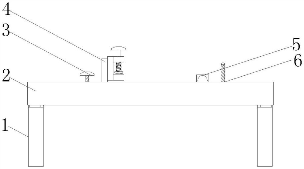
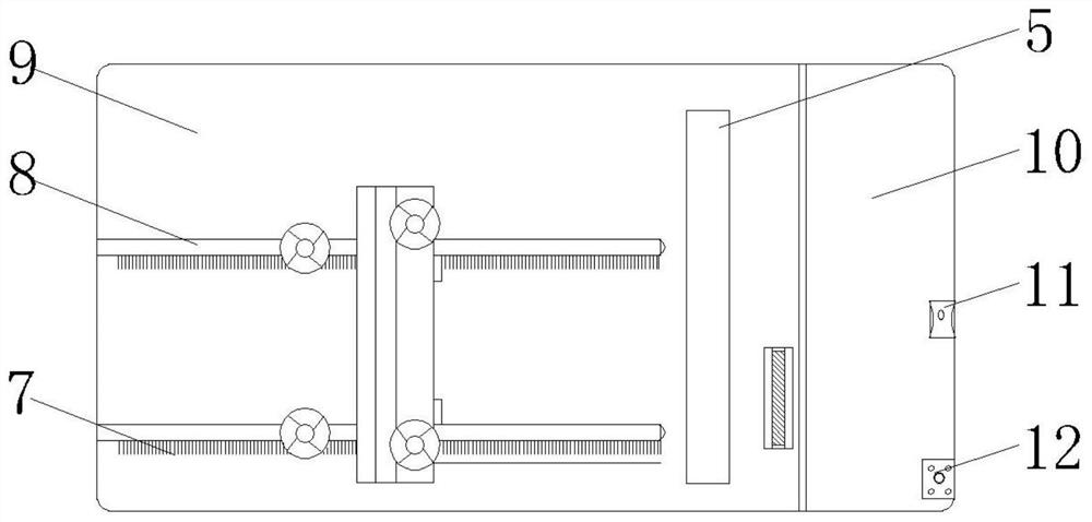
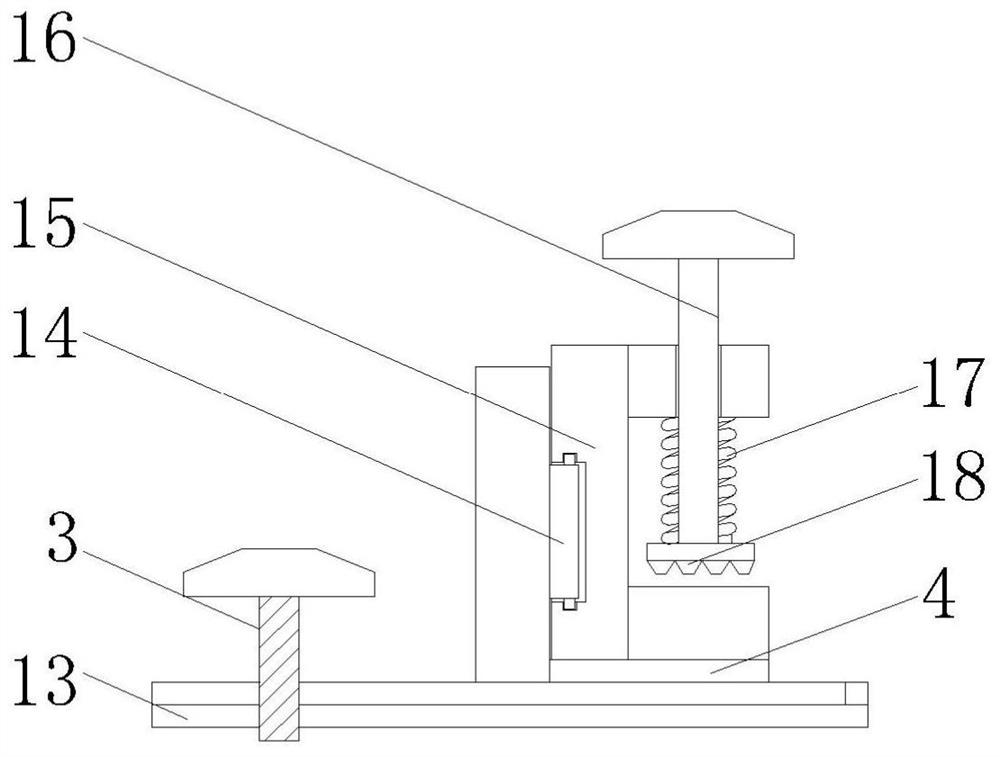
The invention discloses a quantitative wood cutting device. The quantitative wood cutting device comprises supporting legs, an operation table and a cutting tool; a quantitative machining area is arranged on the surface of the part, on one side of the cutting tool, of the operation table; an auxiliary machining area is arranged on the surface of the part, on the other side of the cutting tool, of the operation table; at least two sets of lateral sliding grooves are formed in the surface of the quantitative machining area; stable sliding blocks are arranged on the surfaces of the lateral sliding grooves, and a movable frame is arranged at the top ends of the stable sliding blocks; and a sliding frame is movably arranged on the surface of one side of the movable frame and is a frame-shaped component, an opening in one end of the sliding frame is arranged towards one side, and a limiting mechanism is arranged on the sliding frame. Through the arrangement of a series of structures, the quantitative wood cutting device can conveniently clamp one side of wood, meanwhile, through the lateral and longitudinal sliding groove components, the wood can conveniently move in the left-right and front-back direction, the clamp position can be conveniently adjusted, the quantitative cutting effect is achieved, and the quantitative wood cutting device is suitable for batched cutting operation under the same size.

Description

technical field [0001] The invention relates to the technical field of wood processing, in particular to a wood quantitative cutting device. Background technique [0002] Timber refers to the materials that can be used for construction and manufacturing utensils after preliminary processing after trees are felled. Wood is divided into different types according to different tree species and processed, and is widely used in many fields according to the material properties of wood. , such as housing construction, furniture production, etc. [0003] In the preliminary processing of wood, it is necessary to carry out quantitative cutting of wood. During quantitative cutting, the tools used by workers are different according to the actual situation. The actual structure of this type of cutting table is relatively simple. Generally, workers temporarily assemble it with the help of several wooden boards and cutting machines. If it is necessary to cut wood quantitatively and in batc...

Claims


Application Information

Patent Timeline
Patent Type & Authority Applications(China)
IPC IPC(8): B27C5/02B27C5/06
CPCB27C5/02B27C5/06
Inventor 吴磊
Owner 长兴嘉年华家居有限公司
Why Eureka
Try Eureka