
Built-in test method and system for electromechanical hybrid system

A hybrid system and electromechanical technology, applied in the field of testing, can solve the problems of no systematic design method and no general design method of electromechanical hybrid system, and achieve the effect of accurate fault location

Pending Publication Date: 2021-12-21
BEIJING WATERTEK INFORMATION TECH +1
View PDF0 Cites 0 Cited by
  • Summary
  • Abstract
  • Description
  • Claims
  • Application Information

AI Technical Summary

Problems solved by technology

At present, there is no systematic design method to rely on for the BIT design of the electronic system or the BIT design of the mechanical system. Based on this, there is no general design method for the BIT design of the electromechanical hybrid system.

Method used


Image

  • Built-in test method and system for electromechanical hybrid system
  • Built-in test method and system for electromechanical hybrid system
  • Built-in test method and system for electromechanical hybrid system

Examples


example 1

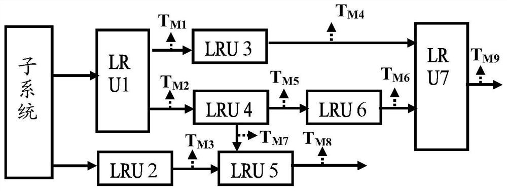
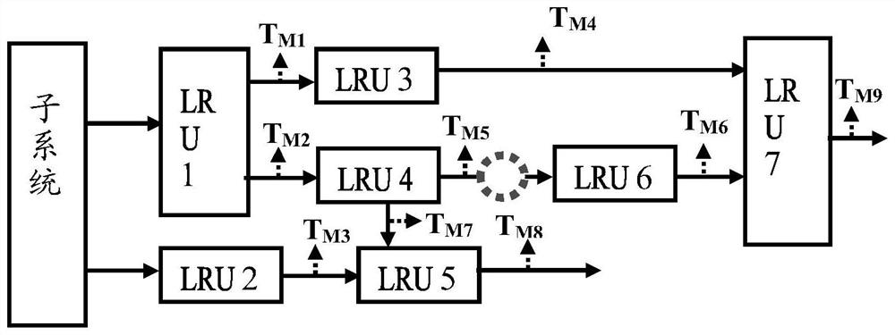
[0117] Example 1, it is assumed that LRU4 faults and LRU6 faults form a fault fuzzy group after fault diagnosis, and there is no hidden fault.

[0118] LRU4 and LRU6 can be isolated by a programmable switch circuit, such as image 3 As shown, the program-controlled switch is transparent and straight-through when the electromechanical hybrid system is working normally through programming settings; when the BIT test is performed, the connection between LRU4 and LRU6 is disconnected through the program-controlled switch circuit (equivalent to isolating the influence of LRU6), and the test T M5 , if T M5 If there is no abnormality, it means that LRU4 is not faulty. The abnormality is caused by the fault of LRU6. Just replace the faulty LRU6 with the non-faulty LRU6. If LRU4 is faulty, replace faulty LRU4 with non-faulty LRU4 and then test T M6 , if T M6 No abnormality indicates that LRU6 is not faulty, if T M6 The exception indicates that LRU6 is faulty. In this way, the prob...

example 2

[0119] Example 2, it is assumed that the LRU4 fault and the LRU6 fault form a fault fuzzy group after fault diagnosis, and the concealed LRU5 fault and LRU7 fault may occur.

[0120] First, determine the LRU in the fault fuzzy group that has a definite fault according to the method of Example 1. Once the faulty LRU is determined, replace and recover the faulty LRU, and then execute the test T M8 , T M9 It can be determined whether LRU5 and LRU7 are faulty, if T M8 output abnormal data, it is determined that the LRU5 is faulty; if T M9 If abnormal data is output, it is determined that the LRU7 is faulty.

example 3

[0121] Example 3, it is assumed that the failure of LRU4 and the failure of LRU6 constitute a multi-LRU failure after fault diagnosis, and a hidden failure of LRU5 and LRU7 may occur.

[0122] After recovering by replacing faulty LRU4 and faulty LRU6, perform test T again M8 , T M9 It can be determined whether LRU5 and LRU7 are faulty, if T M8 output abnormal data, it is determined that the LRU5 is faulty; if T M9 If abnormal data is output, it is determined that the LRU7 is faulty.

[0123] The embodiment of the present application also provides a computer-readable storage medium, where one or more programs are stored in the computer-readable storage medium, and the one or more programs can be executed by one or more processors to implement the following: method described in the preceding examples.

[0124] The embodiment of the present application also provides an in-machine test device for an electromechanical hybrid system, including a memory and a processor, the memor...


PUM


Abstract

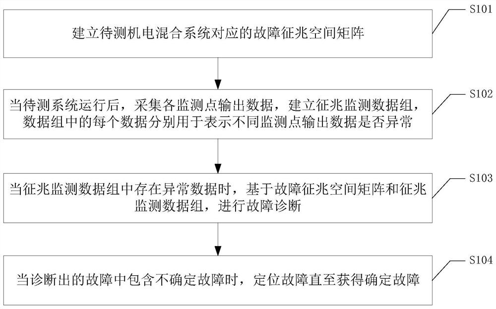
The invention provides a built-in test method and system for an electromechanical hybrid system. The method comprises the steps that a fault symptom space matrix corresponding to the electromechanical hybrid system is established, each row of data of the matrix is used for representing whether output data of all monitoring points of the electromechanical hybrid system are abnormal after a corresponding LRU has a fault, each column of the matrix represents a monitoring point, and different rows of the matrix correspond to different LRUs forming the electromechanical hybrid system; after the electromechanical hybrid system runs, output data of all the monitoring points are obtained, a symptom monitoring data set is established according to the output data of all the monitoring points, and all data in the data set are used for representing whether the output data of different monitoring points are abnormal or not; when abnormal data exists in the data set, fault diagnosis is carried out based on the matrix and the data set, and the diagnosed fault type comprises at least one of a determined fault and an undetermined fault; and when the diagnosed faults include undetermined faults, fault diagnosis is continued until a determined fault is obtained.

Description

Technical field [0001] This article relates to testing technology, specifically an in-machine testing method and system for electromechanical hybrid systems. Background technique [0002] Rapid fault diagnosis of electromechanical hybrid systems usually requires combination with in-machine test BIT (Built-In Test) design. Currently, there is no systematic design method to rely on for the BIT design of electronic systems or the BIT design of mechanical systems. Based on this, there is no universal design method for the BIT design of electromechanical hybrid systems. Contents of the invention [0003] This application provides an in-machine testing method and system for an electromechanical hybrid system, and provides a general design idea for fault location of the electromechanical hybrid system. [0004] The in-machine test methods for electromechanical hybrid systems provided in this application include: [0005] Establish a fault symptom space matrix corresponding to t...

Claims


Application Information

Patent Timeline
Patent Type & Authority Applications(China)
IPC IPC(8): G01M99/00G01D21/02
CPCG01M99/005G01D21/02
Inventor 陈圣俭宋钱骞林枫王志强季德波
Owner BEIJING WATERTEK INFORMATION TECH
Learn More