
Integrated transmission multi-section lifting electric cylinder

An integrated, electric cylinder technology, applied in the direction of electric components, electrical components, electromechanical devices, etc., can solve the problems of low transmission efficiency, inability to effectively guarantee transmission accuracy, equipment verticality, force and accuracy are not very good, etc. , to reduce costs

Pending Publication Date: 2021-12-21
东莞市锐联智能装备有限公司
View PDF5 Cites 0 Cited by
  • Summary
  • Abstract
  • Description
  • Claims
  • Application Information

AI Technical Summary

Problems solved by technology

[0002] The multi-section lifting electric cylinder is driven by a motor, which drives the screw to move. The screw rotates at the original position. The jacking force generated by the thread rotation drives the nut sleeve to move up and down, realizing the telescopic movement of the sleeve. Currently, the multi-section electric cylinder on the market The cylinder is mainly arranged in a trapezoidal shape with multiple screw rods. While the cost is high, due to the influence of the hollow screw rod on the rigidity of the screw rod, the screw rod is prone to deformation, which will affect the overall performance of the electric cylinder, resulting in the verticality of the entire equipment, The force and precision are not very good, resulting in low transmission efficiency and at the same time, the transmission accuracy cannot be effectively guaranteed

Method used


Image

  • Integrated transmission multi-section lifting electric cylinder
  • Integrated transmission multi-section lifting electric cylinder
  • Integrated transmission multi-section lifting electric cylinder

Examples


Embodiment Construction

[0017] In order to make the object, technical solution and advantages of the present invention clearer, the present invention will be further described in detail below in conjunction with the accompanying drawings and embodiments. It should be understood that the specific embodiments described here are only used to explain the present invention, not to limit the present invention.

[0018] In describing the present invention, it should be understood that the terms "length", "width", "upper", "lower", "front", "rear", "left", "right", "vertical", The orientations or positional relationships indicated by "horizontal", "top", "bottom", "inner", "outer", etc. are based on the orientation or positional relationships shown in the drawings, and are only for the convenience of describing the present invention and simplifying the description, and It is not to indicate or imply that the device or element referred to must have a particular orientation, be constructed in a particular orie...


PUM


Abstract

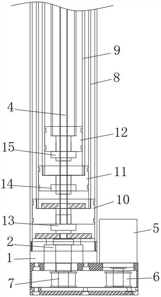
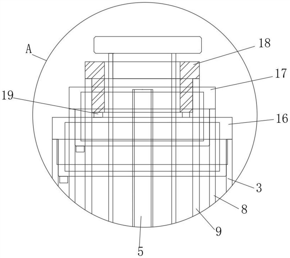
The invention relates to the technical field of lifting electric cylinders, and particularly relates to an integrated transmission multi-section lifting electric cylinder which comprises a mounting end, an outer cylinder barrel and a transmission lead screw. A mounting block is fixedly mounted in the mounting end, the transmission lead screw penetrates through the mounting block and extends into the outer cylinder barrel, and a driving motor is fixedly mounted on one side of the mounting end. A driving gear is fixedly installed at the output end of the driving motor, and a driven gear is fixedly installed at the end, close to the driving motor, of the transmission lead screw. According to the invention, the first lead screw pair, the second lead screw pair and the third lead screw pair are arranged and are matched with the first piston, the second piston and the third piston so that under the driving of the driving motor and the gear, multi-section transmission of the plurality of lead screw pairs on the same lead screw can be realized, and bidirectional limiting lead screw driving is realized; and the problems of a low bearing capacity, low perpendicularity, low precision and the like due to the fact that a traditional electric cylinder is driven by a plurality of hollow lead screws are solved, and the cost is reduced on the whole.

Description

technical field [0001] The invention relates to the technical field of lifting electric cylinders, in particular to an integrated transmission multi-section lifting electric cylinder. Background technique [0002] The multi-section lifting electric cylinder is driven by a motor, which drives the screw to move. The screw rotates at the original position. The jacking force generated by the thread rotation drives the nut sleeve to move up and down, realizing the telescopic movement of the sleeve. The multi-section electric cylinder currently on the market The cylinder is mainly arranged in a trapezoidal shape with multiple screw rods. While the cost is high, due to the influence of the hollow screw rod on the rigidity of the screw rod, the screw rod is prone to deformation, which will affect the overall performance of the electric cylinder, resulting in the verticality of the entire equipment, The force and precision are not very good, which leads to low transmission efficiency...

Claims


Application Information

Patent Timeline
Patent Type & Authority Applications(China)
IPC IPC(8): H02K7/06H02K7/116H02K5/22
CPCH02K7/06H02K7/116H02K5/22
Inventor 刘拥军
Owner 东莞市锐联智能装备有限公司
Learn More