Energy-saving support used for heat transmission pipeline
A technology for conveying pipelines and heat, which is applied in the field of energy-saving supports for heat conveying pipelines. It can solve the problems of difficult transportation and installation, and can not effectively solve the problems of heat energy loss and complex structure of pipe supports. It achieves strong environmental adaptability and is convenient for transportation and installation. , the effect of small contact area
- Summary
- Abstract
- Description
- Claims
- Application Information
AI Technical Summary
Problems solved by technology
Method used
Image
Examples
Embodiment 1
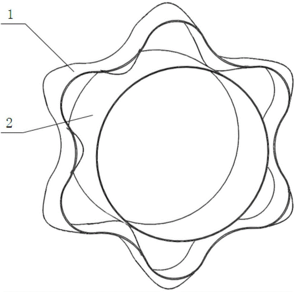
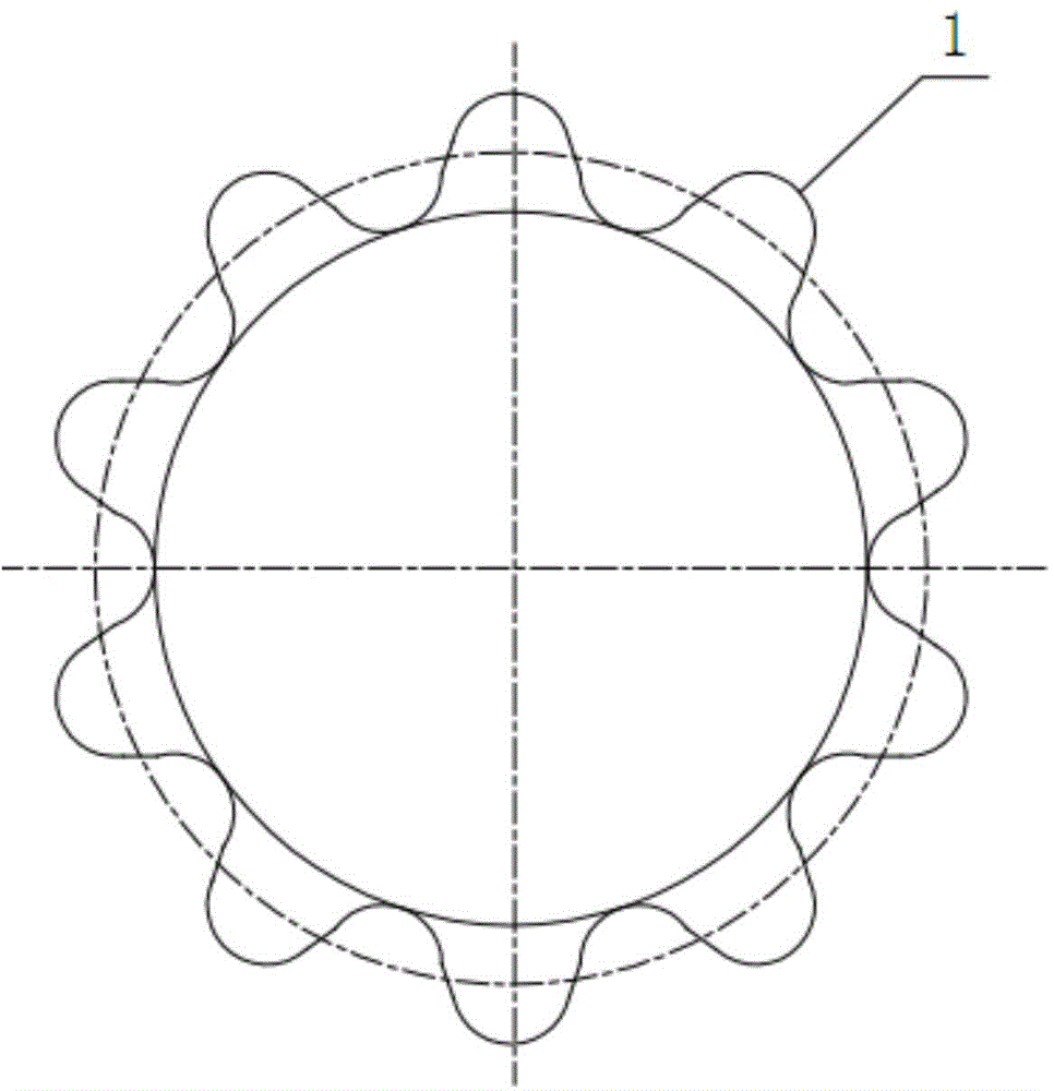
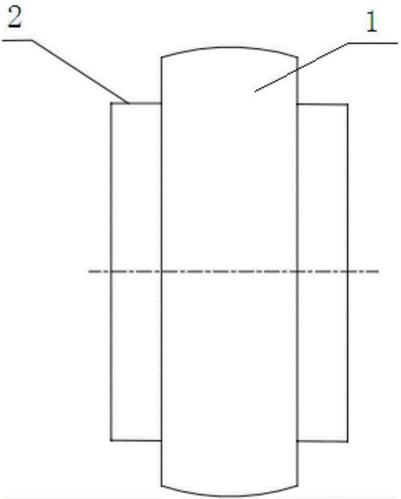
[0032] The energy-saving support for heat transmission pipelines of this embodiment has a structure such as figure 1 , figure 2 and image 3 As shown, it includes a stent body 1 and an inner liner 2 disposed inside the stent body 1 , and both ends of the inner liner 2 are slightly longer than the stent body 1 . The cross-section of the stent body 1 is corrugated radially undulating and uniformly distributed in the circumferential direction. The crests of the corrugations have an arched convex surface a, and the troughs have an arched concave surface b. Two adjacent convex curved surfaces a and concave curved surfaces b form the basic unit of the corrugation. The bracket body 1 of this embodiment is composed of 10 basic units connected smoothly from the end to the end. The convex curved surface a and the concave curved surface in the basic unit The opening of b is opposite, the opening of the convex surface a faces the center of the base circle d, the opening of the concave ...
Embodiment 2
[0037] The difference between this embodiment and Embodiment 1 is that: Figure 10 and Figure 11 As shown, the inner liner 2 is set on the insulation layer 4 of the working pipe 3, the bracket body 1 is placed between the inner liner 2 and the outer sleeve 5, and the space between the bracket body 1 and the inner liner 2 is filled with glass wool for heat preservation. Material 7, and between the bracket body 1 and the outer sleeve 5 is also filled with a certain thickness of glass wool insulation material 7, while leaving a certain thickness of air layer 6 between the bracket body 1 and the outer sleeve 5, that is, the bracket body 1 and the inner liner 2 are placed in the insulation material layer. This structure is suitable for the insulation pipe structure with thicker insulation layer 4 and multi-layer insulation layer 4 . Since the bracket body 1 has a plurality of corrugations, the surface area itself is relatively large. In this assembly structure, all the inner and ...
Embodiment 3
[0039] The difference between this embodiment and Embodiments 1 and 2 is that the stent body is composed of 13 corrugated basic units connected smoothly from head to tail, and the cross-sections of the inner convex curved surface and outer concave curved surface of the basic unit are sinusoidal waveforms, and the axial cross-section for the arc. In addition, the outer diameter of the stent body 1 is the diameter of the circle f formed by the vertices of all the convex curved surfaces on the stent body 1 , and the inner diameter is the diameter of the circle e formed by the vertices of all the concave curved surfaces b on the stent body 1 . (See Figure 5 ).
PUM
 Abstract
Description
Claims
Application Information
 - R&D
- Intellectual Property
- Life Sciences
- Materials
- Tech Scout
- Unparalleled Data Quality
- Higher Quality Content
- 60% Fewer Hallucinations
Browse by: Latest US Patents, China's latest patents, Technical Efficacy Thesaurus, Application Domain, Technology Topic, Popular Technical Reports.
© 2025 PatSnap. All rights reserved.Legal|Privacy policy|Modern Slavery Act Transparency Statement|Sitemap|About US| Contact US: help@patsnap.com


