A flexible optical interconnection method for adjusting the top of the optical mark

An optical interconnection and optical labeling technology, applied in the field of flexible optical interconnection, can solve the problems of difficult signal tracking of optical network switching nodes, increase in the number of nodes, and limited ability to identify services, saving frequency band resources, reducing complexity, and channel redundancy. effect of optimization

Active Publication Date: 2022-02-18
BEIJING UNIV OF POSTS & TELECOMM
View PDF8 Cites 0 Cited by
  • Summary
  • Abstract
  • Description
  • Claims
  • Application Information

AI Technical Summary

Problems solved by technology

[0003] Optical network switching node signals have problems such as difficulty in tracking, limited ability to identify services, and the number of nodes increases significantly with network complexity.

Method used


Image

  • A flexible optical interconnection method for adjusting the top of the optical mark
  • A flexible optical interconnection method for adjusting the top of the optical mark
  • A flexible optical interconnection method for adjusting the top of the optical mark

Examples


Embodiment 1

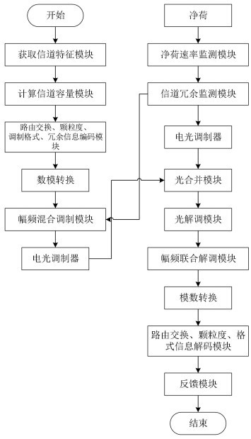
[0087] Embodiment 1: The present invention provides a method that encodes routing and switching node information, bandwidth granularity information, modulation format information, and redundant information, performs digital-to-analog conversion, performs low-speed amplitude-frequency mixed modulation, and electro-optical modulation, and transmits them together with the load. The processing scheme is to encode and modulate the above information into an analog baseband signal without affecting the payload, and transmit it simultaneously with the payload after amplitude-frequency mixed modulation (AM-FM) to the frequency range and then electro-optical modulation. The encoding module adopts linear block code, determines the encoding efficiency according to the current signal-to-noise ratio and the initial encoding length, and optimizes the encoding efficiency under the condition of ensuring a low bit error rate. The digital-to-analog conversion module converts the linear block code...

Embodiment 2

[0088] Embodiment 2: Based on the technical solution provided in Embodiment 1, the present invention provides a scheme for obtaining the channel characteristics of the backbone network / calculating the channel capacity of the backbone network, including:

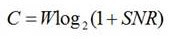
[0089] 1. Calculate the channel capacity C of the backbone network by obtaining the SNR of the backbone network and the channel bandwidth W.

[0090] Shannon's second theorem is used to calculate the channel capacity C of the backbone network, as shown in formula (1).

[0091] (1)

[0092] A coding scheme for routing switching node information, bandwidth granularity information, modulation format information, and redundant information, including:

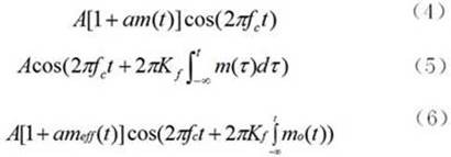
[0093] 1. Obtain routing and switching node information, bandwidth granularity information, modulation format information and redundant information, and perform source coding. The coding rules are shown in formula (2).

[0094] (2)

[0095] In formula (2), n represents the l...


PUM


Abstract

The invention discloses a flexible optical interconnection method for adjusting the top of the optical mark, which includes, according to the existing optical transmission network path planning, encoding and modulating the routing switching node information, granularity information, modulation format information and redundant information, and the service channel The payload of the network is transmitted together to improve the operating efficiency of the optical network; the above-mentioned information is encoded, digital-to-analog converted, and mixed-modulated to add the information to the service channel; this part of the information needs to be transmitted without affecting the original payload. Through signal reception and demodulation, information is obtained at network nodes; thus, service identification, service tracking, and path planning are realized in the optical network, effectively reducing the complexity of the optical transport network; at the same time, the encoding process, modulation process, channel Redundancy and other aspects are optimized to effectively improve spectrum efficiency on the basis of the above requirements.

Description

technical field [0001] The invention relates to the fields of digital communication and optical network, in particular to a flexible optical interconnection method for adjusting the top of an optical mark. Background technique [0002] Digital communication (digital telecommunications) is a communication method that uses digital signals as carriers to transmit information, or uses carrier waves to modulate digital signals before transmission. It can transmit digital signals such as digitized data, as well as analog signals such as digitized voice and images. [0003] Optical network switching node signals have problems such as difficulty in tracking, limited ability to identify services, and the number of nodes increases significantly with network complexity. Contents of the invention [0004] The purpose of the present invention is to provide a scheme for transmitting modulation information and optical network routing and switching node information and bandwidth granular...

Claims


Application Information

Patent Timeline
Patent Type & Authority Patents(China)
IPC IPC(8): H04J3/16
CPCH04J3/1652
Inventor 忻向军张琦王劲然姚海鹏刘博王光全高然田凤田清华
Owner BEIJING UNIV OF POSTS & TELECOMM
Why Eureka
Try Eureka