Crease-resistant fitting equipment for embedded laces of piano panel
A laminating equipment and embedded technology, applied in the field of art education, can solve the problems of wood grain paper and lace damage, scrap wood grain paper and lace, affecting the aesthetics of piano panel lace, etc., so as to reduce production cost and improve yield rate. Effect
- Summary
- Abstract
- Description
- Claims
- Application Information
AI Technical Summary
Problems solved by technology
Method used
Image

Examples
Embodiment
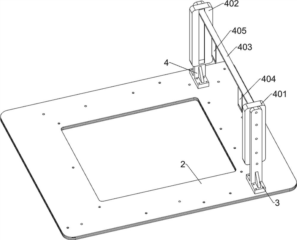
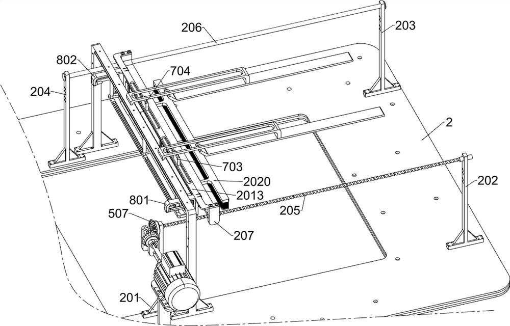
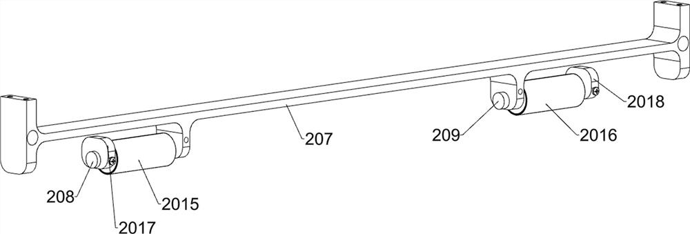
[0041] An anti-wrinkle fitting device for the embedded lace of a piano panel, such as Figure 1-3 As shown, it includes a bottom frame 1, a bottom plate 2, a first riser 3, a second riser 4, a fixing frame 5, a simulated wood grain paper 6, a simulated lace 7, a pressing component, a placing component, a cutting component and a driving component The top of the bottom frame 1 is fixedly connected to the bottom plate 2; the front and rear parts on the left side above the bottom plate 2 are fixedly connected to the first vertical plate 3 and the second vertical plate 4 respectively; ; A pressing assembly for pressing the simulated lace 7 into the simulated wood grain paper 6 is installed above the base plate 2; a placement assembly for fixing the simulated wood grain paper 6 is installed between the base plate 2 and the pressing assembly; A cutting assembly for cutting off the sticker is installed on the side; a driving assembly for driving the equipment is installed on the left ...
PUM
 Abstract
Description
Claims
Application Information