
Air-cooled continuous heat treatment quenching furnace

A quenching furnace and air-cooled technology, which is applied in the field of air-cooled continuous heat treatment quenching furnaces, can solve the problems of slow delivery of workpieces to the rear cooling section, poor quenching effect, and inability to achieve continuous production, and achieves a simple structure layout. Effect

Pending Publication Date: 2021-12-24
BMAN MFG ZHE JIANG
View PDF1 Cites 0 Cited by
  • Summary
  • Abstract
  • Description
  • Claims
  • Application Information

AI Technical Summary

Problems solved by technology

[0006] Aiming at the defects in the prior art, the present invention provides an air-cooled continuous heat treatment quenching furnace, the purpose of which is to solve the problem that although the airtight vacuum quenching furnace in the prior art can realize the rapid cooling effect of the workpiece to be quenched, it cannot realize continuous production, and Although the continuous quenching furnace can realize the continuous production of the quenching process, the quenching effect is not good because the heated workpiece is slowly sent to the rear cooling section through the mesh belt.

Method used


Image

  • Air-cooled continuous heat treatment quenching furnace
  • Air-cooled continuous heat treatment quenching furnace
  • Air-cooled continuous heat treatment quenching furnace

Examples


Embodiment Construction

[0019] Combine below Figure 1-3 The present invention is further described with specific embodiments; the following examples will help those skilled in the art to further understand the present invention, but do not limit the present invention in any form. It should be noted that those skilled in the art can make several modifications and improvements without departing from the concept of the present invention. These all belong to the protection scope of the present invention.

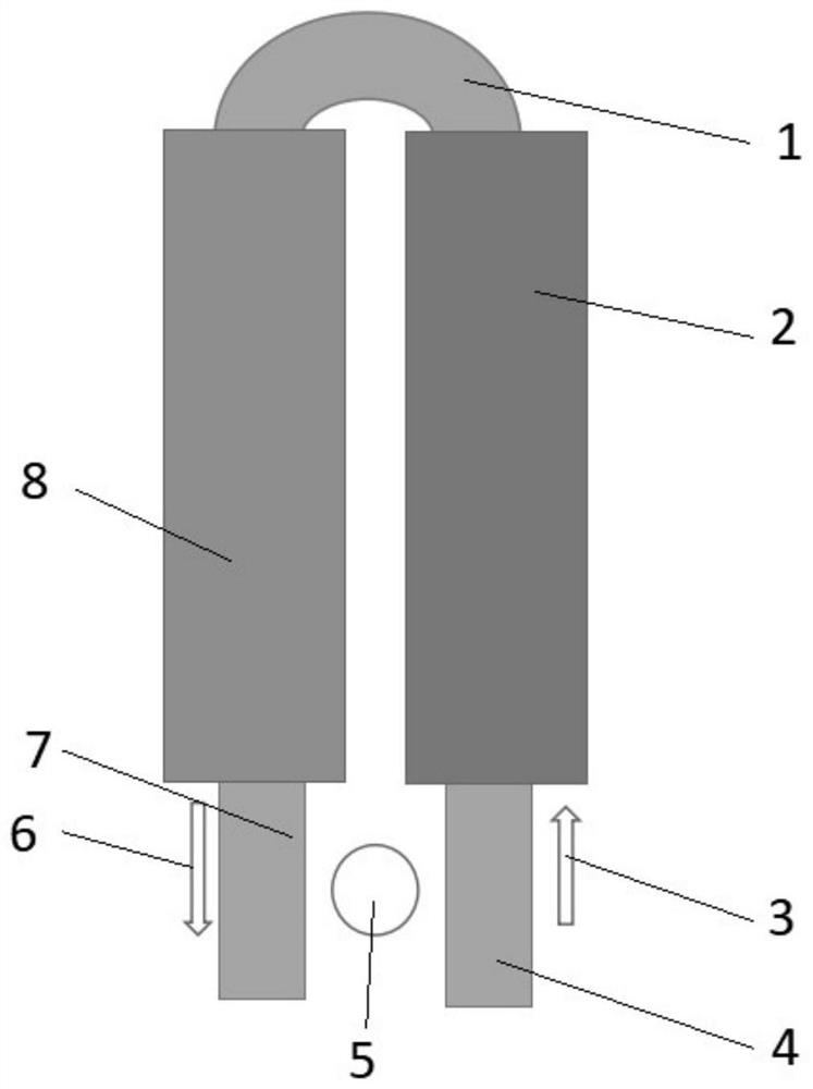
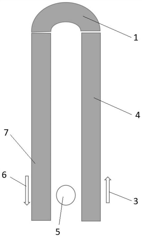
[0020] See attached image 3 , the figure is a schematic structural diagram of a continuous quenching furnace, wherein the workpiece to be quenched enters the heating and heat preservation section 12 from the first feeding direction 13 through the integrated conveyor belt 10, and the workpiece to be quenched is heated to a preset temperature in the heating and heat preservation section 12 temperature and heat preservation, and enter the cooling section 11 along with the integrated conveyor belt 10, b...


PUM


Abstract

The invention discloses an air-cooled continuous heat treatment quenching furnace. The air-cooled continuous heat treatment quenching furnace comprises a U-shaped conveying belt, a heating and heat preservation section, a feeding conveying belt, a discharging conveying belt and a quenching section. The starting end and the tail end of the U-shaped conveying belt are both horizontally arranged. The feeding conveying belt and the discharging conveying belt are both linear conveying belts. The discharging end of the feeding conveying belt abuts against the starting end of the U-shaped conveying belt. The feeding end of the discharging conveying belt abuts against the tail end of the U-shaped conveying belt. The heating and heat preservation section is arranged in the middle of the feeding conveying belt. The quenching section is arranged in the middle of the discharging conveying belt. The problems that in the prior art, although a closed vacuum quenching furnace can achieve the quenching effect of a to-be-quenched part, continuous production cannot be achieved, and although a continuous quenching furnace can achieve continuous production of the quenching process, due to the fact that a heated workpiece is slowly conveyed to a rear section cooling section through a mesh belt, the quenching effect is poor are solved.

Description

technical field [0001] The invention belongs to the field of heat treatment processing equipment, and relates to a heat treatment quenching furnace structure, in particular to an air-cooled continuous heat treatment quenching furnace, which realizes rapid cooling and quenching of quenched parts and continuous production function, and solves the problem of existing Although the airtight vacuum quenching furnace in the technology can realize the rapid cooling effect of the workpiece to be quenched, it cannot realize continuous production. Although the continuous quenching furnace can realize the continuous production of the quenching process, the workpiece is slowly sent to the rear cooling section through the mesh belt after heating. Causes the problem that the rapid cooling effect is not good. Background technique [0002] Today's heat treatment furnace equipment can be roughly divided into the following two types: one is a closed vacuum quenching furnace, and the other is a...

Claims


Application Information

Patent Timeline
Patent Type & Authority Applications(China)
IPC IPC(8): C21D9/00C21D1/74C21D1/62
CPCC21D9/0062C21D1/74C21D9/0018C21D1/62
Inventor 简煜璋王伟
Owner BMAN MFG ZHE JIANG
Learn More