
Oil-immersed transformer capable of changing temperature of oil medium

An oil-immersed transformer, oil-medium technology, applied in transformer/inductor housing, transformer/inductor cooling, transformer/reactor installation/support/suspension, etc. The problem of low heat dissipation efficiency of the radiator

Pending Publication Date: 2022-04-08
天宏电力科技有限公司
View PDF0 Cites 0 Cited by
  • Summary
  • Abstract
  • Description
  • Claims
  • Application Information

AI Technical Summary

Problems solved by technology

[0003] The purpose of the present invention is to address the deficiencies of the prior art, and provide an oil-immersed transformer that changes the temperature of the oil medium, so as to solve the above-mentioned problems in the background technology. , while the heat dissipation efficiency of the chip radiator is low, and the transformer often has to stop running because of the high oil temperature, otherwise it may cause the performance of the transformer to drop, resulting in waste of the power grid, and even cause the temperature of the transformer to be too high, causing the transformer components to burn out. At the same time, with the emergence of extreme weather in recent years, the lowest temperature in many areas has been lower than the oil freezing point of the oil-immersed transformer, and the oil-immersed transformer cannot be started, which affects the normal operation of the power system. The transformer is installed in the middle of the installation column as a whole, and the high-voltage line is connected again, which causes the operator to repeatedly operate and install on both sides of the oil-immersed transformer through auxiliary equipment, which causes the problem of low overall installation efficiency

Method used


Image

  • Oil-immersed transformer capable of changing temperature of oil medium
  • Oil-immersed transformer capable of changing temperature of oil medium
  • Oil-immersed transformer capable of changing temperature of oil medium

Examples


Embodiment Construction

[0037] The following will clearly and completely describe the technical solutions in the embodiments of the present invention with reference to the accompanying drawings in the embodiments of the present invention. Obviously, the described embodiments are only some, not all, embodiments of the present invention. Based on the embodiments of the present invention, all other embodiments obtained by persons of ordinary skill in the art without making creative efforts belong to the protection scope of the present invention.

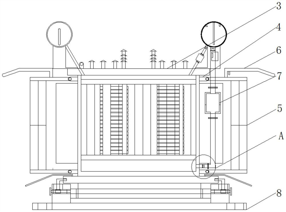
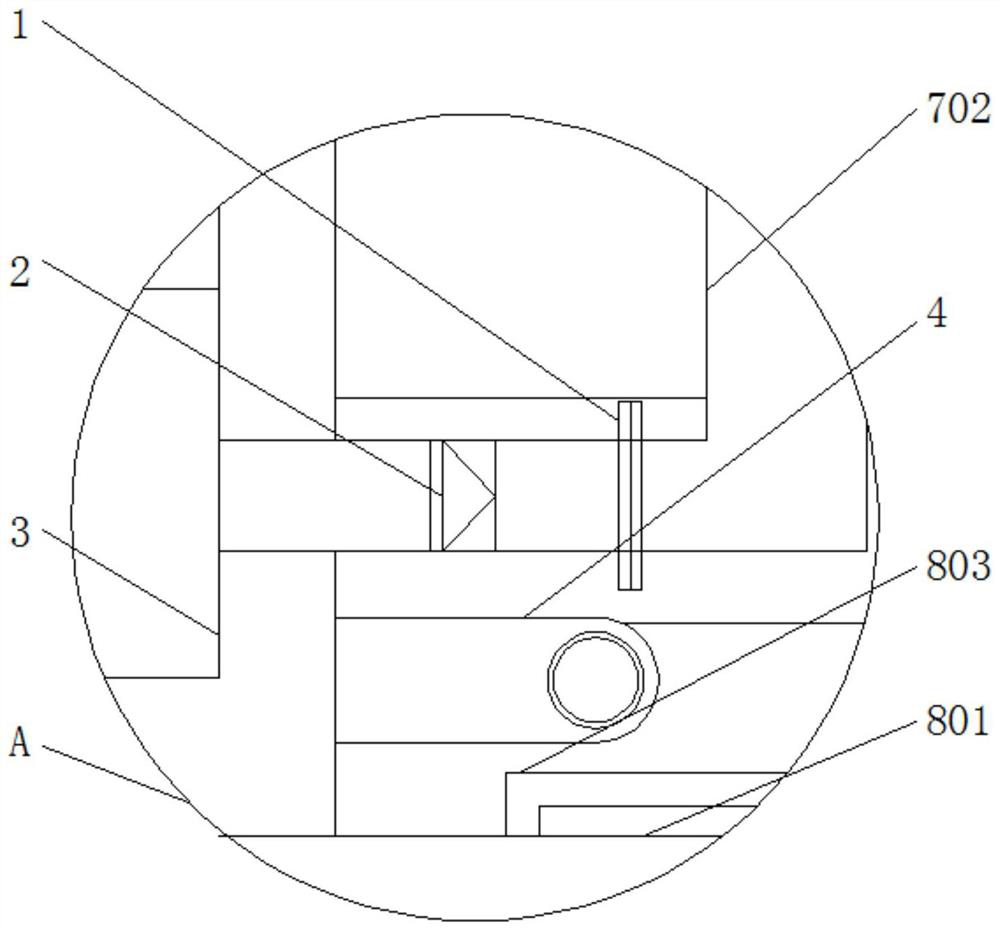
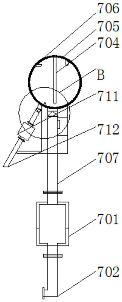
[0038] see Figure 1-7 , the present invention provides a technical solution: an oil-immersed transformer that changes the temperature of the oil medium, such as figure 1 and figure 2 As shown, the first electric check valve 2 is fixed at one end of the oil outlet flange pipe 1, and the other end of the oil outlet flange pipe 1 is inlaid and fixedly connected with the lower side of the transformer body 3, and a single hole is fixed on one side of the transfo...


PUM


Abstract

The invention discloses an oil-immersed transformer capable of changing the temperature of an oil medium, which comprises an oil outlet flange pipe, a cooling fan, a first baffle plate, an oil medium heating device and a rotary mounting locking device, a first electric one-way valve is fixed at one end in the oil outlet flange pipe, and single-hole connecting piece groups are fixed at two sides of a transformer body. The two sides of each cooling fan are fixedly connected with the other single-opening connecting piece set, the cooling fans penetrate through the single-opening connecting piece sets through fixing bolts to be installed on the two sides of the transformer body, the oil-immersed transformer capable of changing the temperature of the oil medium is provided with the first baffle, and the first baffle plays a role in shielding rain for the cooling fans; therefore, the situation that rainwater flows into the cooling fan and makes contact with a circuit, meanwhile, the circuit in the cooling fan is prone to being disconnected or short, the effect of rapidly cooling the transformer body through the cooling fan is affected, and the maintenance and replacement cost of the cooling fan is increased is avoided.

Description

technical field [0001] The invention relates to the technical field of oil-immersed transformers, in particular to an oil-immersed transformer for changing the temperature of an oil medium. Background technique [0002] The oil-immersed transformer is a key equipment in the process of power transmission, which plays an important role in regulating the grid voltage. The oil-immersed transformer has a relatively simple structure and good safety, and occupies a relatively high position in my country's low- and medium-voltage output. share, but the oil-immersed transformers currently used generally use chip radiators, and the cooling efficiency of chip radiators is low. The transformer often has to stop running because of the high oil temperature, otherwise it may cause the performance of the transformer to decline. It causes the power grid to be wasted, and even causes the temperature of the transformer to be too high, causing the components of the transformer to burn out. The tr...

Claims


Application Information

Patent Timeline
IPC IPC(8): H01F27/08H01F27/40H01F27/29H01F27/06H01F27/02
Inventor 李蒙蒙
Owner 天宏电力科技有限公司
Learn More