Device for improving mixing efficiency of slurry and soil of mixing pile

A mixing efficiency, cement-soil mixing pile technology, applied in soil protection, sheet pile walls, construction, etc., can solve the problems of inability to spray grout, failure to achieve uniform mixing of grout and reinforced soil, blockage, etc., to ensure spraying. The effect of pulp uniformity

Pending Publication Date: 2021-12-24
南京瑞迪建设科技有限公司 +1
View PDF9 Cites 0 Cited by
  • Summary
  • Abstract
  • Description
  • Claims
  • Application Information

AI Technical Summary

Problems solved by technology

[0002] During the construction of traditional cement-soil mixing piles, there are problems of uneven grout content at different depths and blockage of the spray hole. The uniformity of the middle and lower parts is poor. As the depth increases, the uniformity becomes worse and worse, which seriously affects the quality of the pile body and thus affects the quality of the project.
The main technical problem involved is that as the treatment depth increases, the surrounding soil pressure increases, resulting in the inability of continuous and effective spraying of the spray hole, or even blockage, which greatly affects the quality of the pile body
On the other hand, the traditional spray hole is set on the side of the stirring shaft. As the depth increases, the surrounding soil pressure increases, and the slurry sprayed from the spray hole flows upward along the direction of the least resistance, that is, the gap between the stirring shaft and the soil. , the grout flowed out from the ground, resulting in insufficient grout content in the soil to be reinforced, or even no grout supply, failing to achieve the goal of uniform mixing of grout and reinforced soil, seriously affecting the quality of the pile body, and causing grout to be wasted

Method used


Image

  • Device for improving mixing efficiency of slurry and soil of mixing pile
  • Device for improving mixing efficiency of slurry and soil of mixing pile
  • Device for improving mixing efficiency of slurry and soil of mixing pile

Examples


Embodiment 1

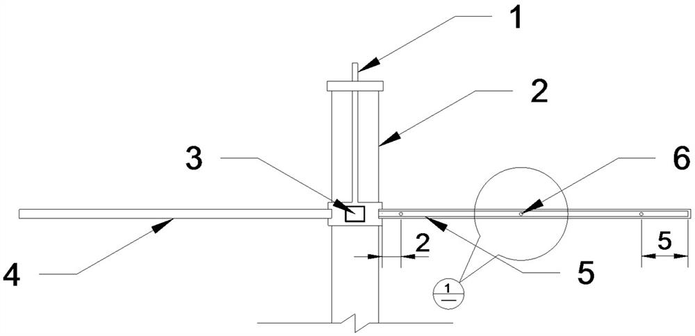
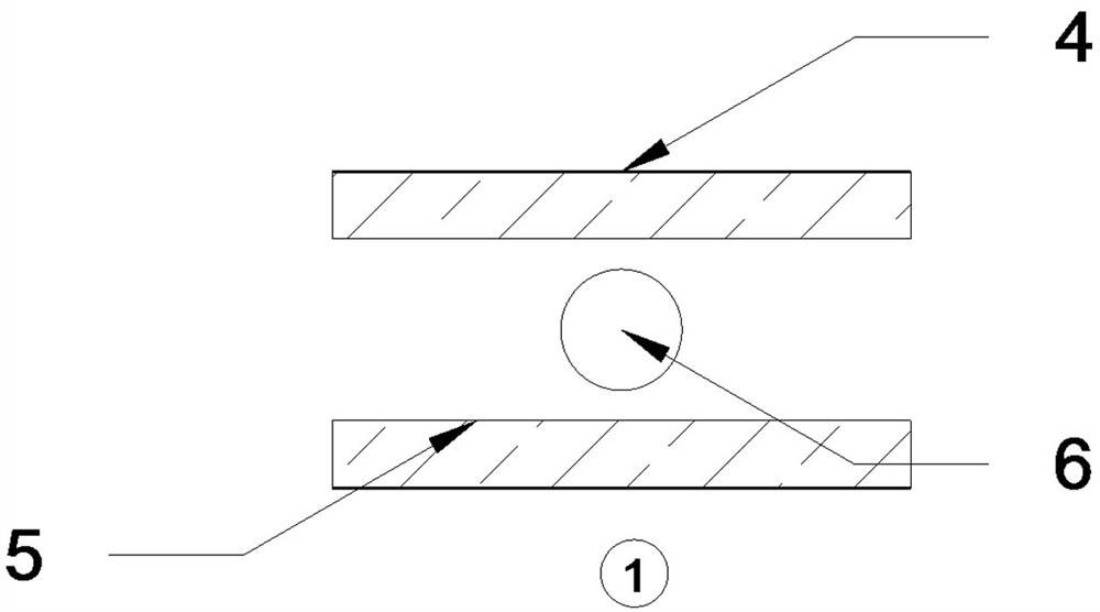
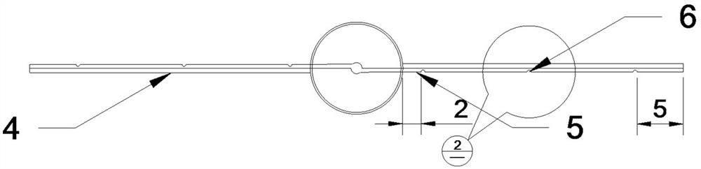
[0033] Embodiment one, with reference to figure 1 : A device for improving the uniformity of cement-soil mixing pile slurry in soft soil reinforcement, including a slurry delivery pipe 1, a stirring shaft 2, a pressure sensor 3, a stirring blade 4, a spray pipe 5, a spray hole 6, and an elastic stop Back to valve 7.

[0034] When the mixer reaches the designated pile position, the center of the mixing head is aligned with the designed pile position. The mixer sinks while stirring, and the sinking speed is controlled by the motor. When the mixer sinks to a certain depth, the slurry is mixed according to the mix ratio determined by the design pile strength requirements. The amount of slurry is determined by the spraying in the construction process. The number of times is determined, and the slurry is poured into the collecting hopper before grouting. After the mixer sinks to the design depth, turn on the mud pump to inject the slurry into the foundation for soft soil reinforce...


PUM


Abstract

The invention discloses a device for improving the mixing efficiency of slurry and soil of a mixing pile. The device is mainly characterized in that slurry spraying holes are formed in the rear sides of mixing blades, and gaps formed by the viscosity of soft soil on the non-cutting sides of the blades after the soft soil is cut by the mixing blades are utilized, so that the slurry is conveniently and uniformly sprayed out in the axial direction of the mixing blades, and meanwhile, the problems that existing mixing equipment is uneven in slurry spraying and even the slurry spraying holes are often blocked are solved; the slurry spraying holes are controlled to be opened and closed by utilizing an elastic check valve, so that the slurry is prevented from being wasted; and the pressure of the slurry spraying holes is monitored in real time by means of a pressure sensor, so that the slurry conveying pressure of a slurry pump is adjusted, the stability of the pressure of the slurry spraying holes is guaranteed, and the slurry is prevented from being wasted due to the fact that the pressure is too large and the slurry supply amount is insufficient due to the fact that the pressure is too small.

Description

technical field [0001] The invention belongs to the technical field of ground pile construction, and in particular relates to a device for improving the mixing efficiency of cement-soil mixing pile slurry and soil, and an improving method thereof. Background technique [0002] During the construction of traditional cement-soil mixing piles, there are problems of uneven grout content at different depths and blockage of the spray hole. The uniformity of the middle and lower parts is poor. As the depth increases, the uniformity becomes worse and worse, which seriously affects the quality of the pile body, and then affects the quality of the project. The main technical problem involved is that as the treatment depth increases, the surrounding soil pressure increases, resulting in the inability of continuous and effective spraying of the spray hole, or even blockage, which greatly affects the quality of the pile body. On the other hand, the traditional spray hole is set on the s...

Claims


Application Information

Patent Timeline
IPC IPC(8): E02D5/46E02D3/12
CPCE02D5/46E02D3/12
Inventor 王东利杨杰陈和平黄汉雄陈晓鹏郑海彬赵伟郭颖钊康虹岩魏鹏飞赵旭东李景林张浩
Owner 南京瑞迪建设科技有限公司
Why Eureka
Try Eureka