Roof mounting method

An installation method and roof technology, which can be applied to roofs, buildings, building components, etc., can solve problems such as the inability to meet the construction needs of larger spans and heavier roofs

Pending Publication Date: 2021-12-24
CHINA CONSTR STEEL STRUCTURE TIANJIN CO LTD
View PDF5 Cites 2 Cited by
  • Summary
  • Abstract
  • Description
  • Claims
  • Application Information

AI Technical Summary

Problems solved by technology

[0004] Therefore, the technical problem to be solved by the present invention is to overcome the defects in the prior art that cannot meet the construction requirements of larger span and heavier roofs, so as to provide a roof installation method

Method used


Image

  • Roof mounting method
  • Roof mounting method
  • Roof mounting method

Examples


Embodiment

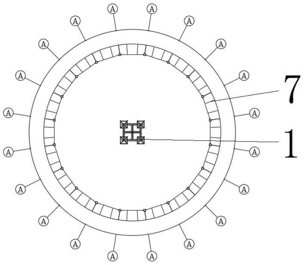
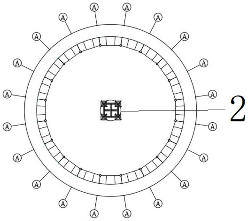
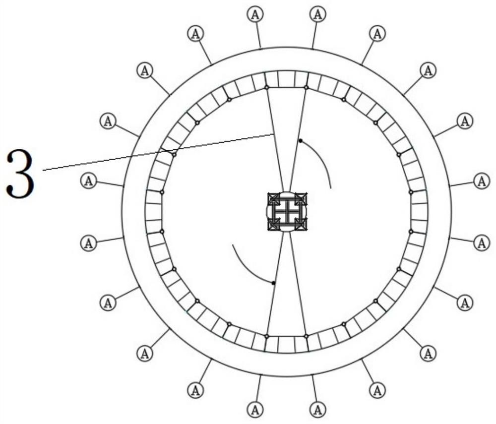
[0061] This embodiment provides as Figure 1 to Figure 20 A roof installation method shown includes the following steps:

[0062] Such as figure 1 As shown, install the construction support platform 1: measure and position through the total station, where as Figure 8 As shown, the construction support platform 1 includes multiple sets of lattice support frames 11, horizontal connecting beams 12, diagonal bars 13 and a construction operation platform. The beam 12, the oblique bar 13 and the lattice support frame 11 are welded and fixed; if Figure 8 with Figure 11 As shown, the operating platform is arranged on the top of the lattice type support frame 11, the operation platform includes a skirting board 141, a steel wire mesh sheet 142 and a guardrail 143, the skirting board 141 is arranged on the top of the lattice type supporting frame 11, and the guardrail 143 is located on the skirting board 141 , The steel wire mesh sheet 142 is set in the guardrail 143, the skirtin...


PUM


Abstract

The invention discloses a roof mounting method. The roof mounting method comprises the following steps that a roof ring truss is mounted; installing a beam string structure, wherein the beam string structure is connected with the roof ring truss and the outer supporting frame; installing a beam string structure web member, wherein the beam string structure web member is arranged on the beam string structure; and inhaul cables are installed, wherein the inhaul cables are connected with the roof ring truss, the beam string structure web members and the outer supporting frame. According to the roof mounting method of the step, enough force can be provided by mounting the beam string structure and the inhaul cables, and therefore the building requirements of larger-span and heavier roofs are met.

Description

technical field [0001] The invention relates to the technical field of buildings, in particular to a roof installation method. Background technique [0002] With the rapid development of my country's economy, the roof of traditional large-scale construction projects adopts a single structural form of reinforced concrete, which cannot meet further requirements in terms of functional requirements or aesthetic performance, which makes the shape more complex. The production of the roof. [0003] The prior art discloses a roof installation method, which includes the following steps: first, install the outer ring steel beam on the pre-installed steel column, then install the support platform according to the installation position of the pressure ring, and then install the support platform on the support platform Place a jack on each top platform on the top, then place the pressure ring on the jack, adjust the working height of the jack to make the pressure ring reach the design el...

Claims


Application Information

Patent Timeline
Patent Type & Authority Applications(China)
IPC IPC(8): E04B1/35E04B7/14
CPCE04B1/35E04B7/14E04B2001/3583
Inventor 周元智梅超陈华周郭发强唐永忠郭浩浩
Owner CHINA CONSTR STEEL STRUCTURE TIANJIN CO LTD
Why Eureka
Try Eureka