
Water dispenser control method, control system and water dispenser

A control method and technology for a control system, applied in beverage preparation devices, household appliances, applications, etc., can solve problems such as water flow obstruction, reduce the maximum water flow of the machine, and achieve the effect of reducing design and production costs

Pending Publication Date: 2021-12-28
ZHEJIANG SHAOXING SUPOR DOMESTIC ELECTRICAL APPLIANCE CO LTD
View PDF0 Cites 0 Cited by
  • Summary
  • Abstract
  • Description
  • Claims
  • Application Information

AI Technical Summary

Problems solved by technology

[0003] In view of this, the embodiment of the present invention provides a water dispenser control method, a control system and a water dispenser to solve the problem that the water flow detection device added in the instant water dispenser in the prior art to prevent dry burning will affect the water flow. Obstruction effect, to a certain extent reduces the technical problem of the maximum water flow of the machine

Method used


Image

  • Water dispenser control method, control system and water dispenser
  • Water dispenser control method, control system and water dispenser
  • Water dispenser control method, control system and water dispenser

Examples


Embodiment 1

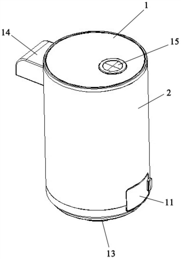
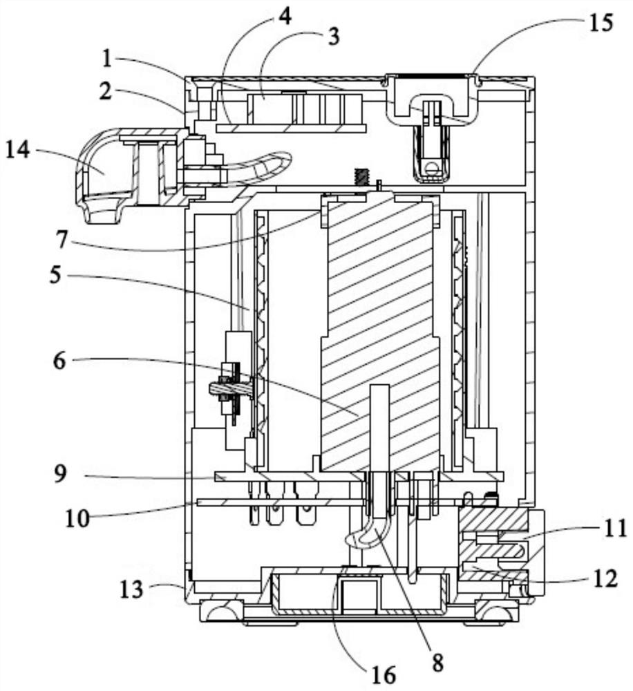
[0058] Such as figure 1 and figure 2 As shown, Embodiment 1 of the present invention discloses an instant water dispenser, comprising: an upper cover 1, a housing 2, a screen partition 3, a main control circuit board 4, a heater assembly 5, a water pump 6, and a water pump sealing ring 7 , waterway 8, plug assembly 9, power circuit board 10, socket dust cover 11, three-pin socket 12, lower cover 13, water outlet cover 14, water inlet dust cover 15 and grounding device 16.

[0059] Wherein, the upper cover 1 closes the upper end of the shell 2 , and the lower cover 13 closes the lower end of the shell 2 . The screen partition 3 and the main control circuit board 4 are assembled together and installed on the upper inner wall of the housing 2. When the main control circuit board 4 needs to send a water shortage signal, the screen partition 3 shows water shortage. The heater assembly 5, the water pump 6 and the insert assembly 9 are assembled together, the insert assembly 9 is ...

Embodiment 2

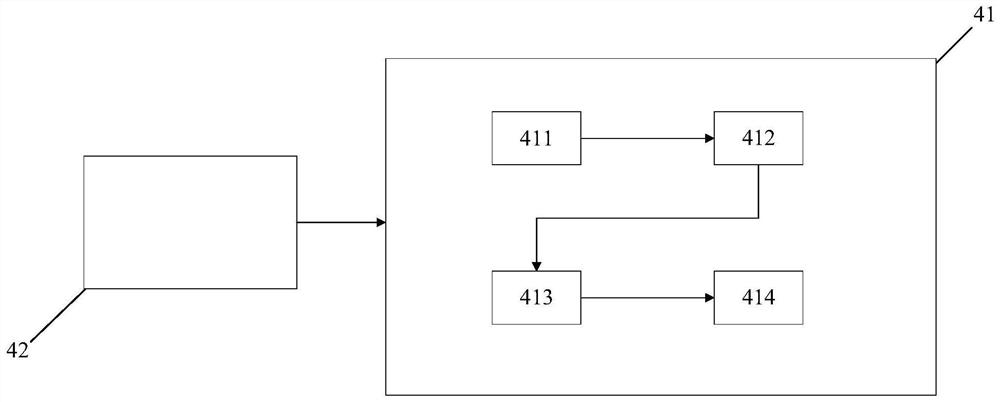
[0061] Such as image 3 As shown, Embodiment 2 of the present invention provides a water dispenser control system, which is installed on the main control circuit board of the water dispenser disclosed in Embodiment 1 above.

[0062] The control system includes a control circuit 41 and a control unit 42. The control circuit 41 is controlled by the control unit 42. Since the load voltage of the water pump 6 is different under the conditions of water flow and no water flow in the waterway 8, by judging the 6 to determine the load voltage of the water pump 6, and then determine whether there is water flow in the waterway 8. The control method has fast response speed, is not affected by water flow velocity, and can provide water shortage warning in time and implement protection measures such as preventing dry burning.

[0063] The control circuit 41 includes a water inlet module 411, a current detection module 412, an algorithm module 413 and a water shortage prompt module 414; th...

Embodiment 3

[0066] Embodiment 3 of the present invention provides a computer-readable storage medium on which the water dispenser control system disclosed in Embodiment 2 above is stored. When the water dispenser control system is executed by a processor, the following implementations are implemented: The water dispenser control method disclosed in Embodiment 2 of the text.


PUM


Abstract

The embodiment of the invention discloses a water dispenser control method, a control system and a water dispenser. During running and detecting whether water flow exists in a water path, because a water flow detection device is not arranged, a current detection module is used for detecting whether the water flow exists in the water path by detecting the magnitude of current in a water pump, the water outlet of the water dispenser is not influenced, influence of water output speed of the water dispenser is avoided, water shortage of the water dispenser can be rapidly detected, protection is conducted in time, and reminding is given out; and meanwhile, the water dispenser does not need to be additionally provided with additional devices, and the interior of the water dispenser is not limited by the space structure, so that the design and production cost is reduced.

Description

【Technical field】 [0001] The invention relates to the technical field of water dispensers, in particular to a water dispenser control method, control system and water dispenser. 【Background technique】 [0002] Most of the tankless portable instant water dispensers currently on the market are composed of heating components, water pumps, control components, and water flow detection components. When in use, most of the existing tankless portable instant water dispensers use water flow detection devices such as flow meters to detect whether the machine is short of water, so as to provide warnings and prevent dry burning. However, this detection method needs to add a water flow detection device, which not only makes the design of the machine more complicated and the cost is higher, but also hinders the water flow due to its working principle, which reduces the maximum flow of the machine to a certain extent. At the same time, the reaction speed of the device to detect the water ...

Claims


Application Information

Patent Timeline
Patent Type & Authority Applications(China)
IPC IPC(8): A47J31/52A47J31/46A47J31/00
CPCA47J31/52A47J31/525A47J31/46A47J31/468A47J31/00
Inventor 林鹏超黄小承
Owner ZHEJIANG SHAOXING SUPOR DOMESTIC ELECTRICAL APPLIANCE CO LTD
Learn More