Lower notch angle compensation device for bending machine and implementation method of lower notch angle compensation device
An angle compensation and bending machine technology, which is applied in the field of notch angle compensation, can solve the problems of reduced efficiency of bending workpieces and cumbersome steps to replace notch, so as to improve the bending efficiency, reduce the probability of misalignment, the degree of misalignment, and the compression resistance. Stability-enhancing effect
- Summary
- Abstract
- Description
- Claims
- Application Information
AI Technical Summary
Problems solved by technology
Method used
Image
Examples
Embodiment 1
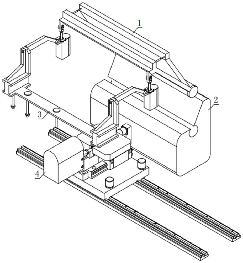
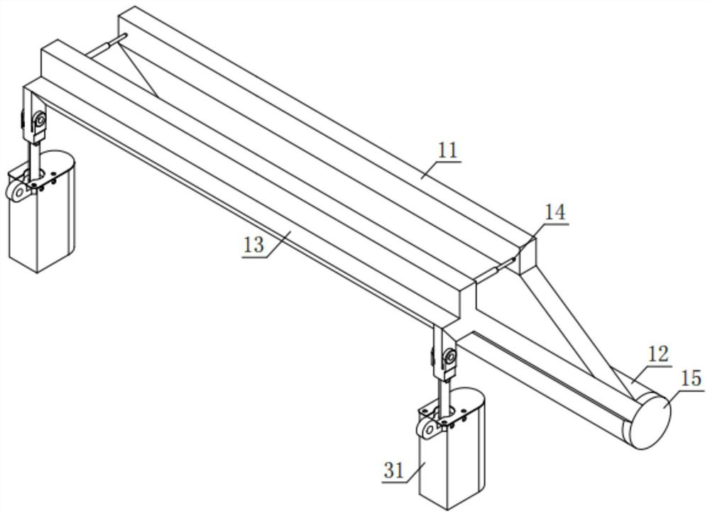
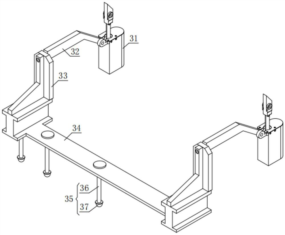
[0035] refer to Figure 1 to Figure 2, a lower notch angle compensation device for a bending machine, comprising an angle compensation mechanism 1, a lower die mold 2, an adjustment mechanism 3 and a moving base 4, an adjustment mechanism 3 is installed on the upper end of the movement base 4, and the adjustment mechanism 3 and the angle compensation The mechanism 1 is connected to each other, and the angle compensation mechanism 1 is connected to the lower die mold 2; the angle compensation mechanism 1 includes a panel 11, a central shaft 12, a U-shaped bracket 13 and a hydraulic cylinder 14, and the lower end of the panel 11 is fixedly connected with a central shaft 12, U The middle part of the lower end of the U-shaped bracket 13 is rotatably connected with the central axis 12, and the upper end of the U-shaped bracket 13 is connected with the panel 11 through the hydraulic cylinder 14; the lower end of the U-shaped bracket 13 extends downward to form side ears 15, and the t...
Embodiment approach
[0039] refer to Figure 7 , in order to better demonstrate the implementation process of the lower notch angle compensation device for bending machines, this embodiment now proposes an implementation method for the lower notch angle compensation device for bending machines, including the following steps:
[0040] S101: The driving mechanism drives the main sliding plate 42 to slide to the right end of the lower mold 2 until the projection of the angle compensation mechanism 1 along the vertical direction is located at the right end of the lower mold 2;
[0041] S102: the adjustment mechanism 3 drives the angle compensation mechanism 1 to move downward until the central axis 12 is aligned with the notch 21; specifically, the lifting cylinder 31 in the adjustment mechanism 3 drives the angle compensation mechanism 1 to move downward;
[0042] S103: The driving mechanism drives the main sliding plate 42 to slide to the left end of the lower die 2 until the central axis 12 is comp...
Embodiment 2
[0045] The difference between this embodiment and Embodiment 1 is that in this embodiment, a wedge block 23 is added, and the position between the lower mold 2 and the panel 11 is fixed by the wedge block 23, thereby improving the V-shaped groove in the process of bending the workpiece. Compressive performance, and at the same time can avoid misalignment between the lower die mold 2 and the panel 11.
[0046] refer to Figure 8 , the top wall of the lower mold 2 and the lower inner wall of the panel 11 are provided with oblique conical teeth 22, and a wedge block 23 is provided between the lower mold 2 and the panel 11, and the outer surface of the wedge block 23 is provided with The obliquely tapered groove 24 , the obliquely tapered groove 24 and the obliquely tapered teeth 22 engage with each other.
[0047] refer to Figure 9 , in order to better demonstrate the implementation process of the lower notch angle compensation device for bending machines, this embodiment now ...
PUM
 Abstract
Description
Claims
Application Information
 - R&D
- Intellectual Property
- Life Sciences
- Materials
- Tech Scout
- Unparalleled Data Quality
- Higher Quality Content
- 60% Fewer Hallucinations
Browse by: Latest US Patents, China's latest patents, Technical Efficacy Thesaurus, Application Domain, Technology Topic, Popular Technical Reports.
© 2025 PatSnap. All rights reserved.Legal|Privacy policy|Modern Slavery Act Transparency Statement|Sitemap|About US| Contact US: help@patsnap.com


