Blast furnace material distribution folding chute and blast furnace material distribution equipment

A cloth chute and cloth technology, applied in the direction of bell and funnel arrangement, etc., can solve the problems of affecting the quality of cloth, increasing force and loss of kinetic energy, and large deceleration, so as to improve the quality of cloth and reduce force and loss of kinetic energy.

Pending Publication Date: 2021-12-28
湖南德尚源耐磨工业有限公司
View PDF0 Cites 0 Cited by
  • Summary
  • Abstract
  • Description
  • Claims
  • Application Information

AI Technical Summary

Problems solved by technology

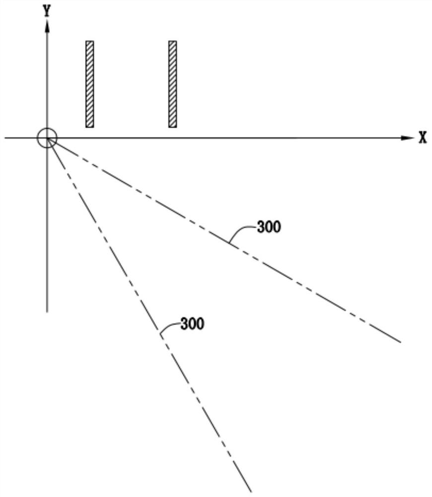
[0003] like figure 1 and figure 2 As shown in the prior art, the contour of the material chute structure on the symmetrical section of the blast furnace distribution chute 300 is a straight line. When the blast furnace distributes material from the center to the furnace wall, the amount of material distribution increases quadratically, but the profile of the material chute gradually changes from vertical to vertical. Horizontal swing, the minimum angle with the horizontal plane is about 30°, at this time, the amount of cloth required is the largest; but the angle at which the material hits the profile of the sliding material structure also reaches a maximum of about 60°, and the impact causes the largest loss of kinetic energy and the largest deceleration of the material. The velocity component in the line direction is fur

Method used


Image

  • Blast furnace material distribution folding chute and blast furnace material distribution equipment
  • Blast furnace material distribution folding chute and blast furnace material distribution equipment
  • Blast furnace material distribution folding chute and blast furnace material distribution equipment

Examples


Example Embodiment

[0032] In order to better understand the technical solution in the present application, the technical solutions in the present application will be apparent to those skilled in the present application. , Not all of the embodiments. Based on the embodiments in the present application, one of ordinary skill in the art is in the scope of the present application without making creative labor premistence.

[0033] It should be noted that when the element is referred to as "fixed to" or "set" on another element, it can be directly placed directly on another component directly; when a component is called "connection As "another component, it can be directly connected to another component or indirectly connected to another element.

[0034] It should be noted that the structure, proportion, size, etc., which are shown in the drawings of this specification, are only used in conjunction with the contents disclosed in the specification for familiar with those skilled in the art, and is not in...


PUM


Abstract

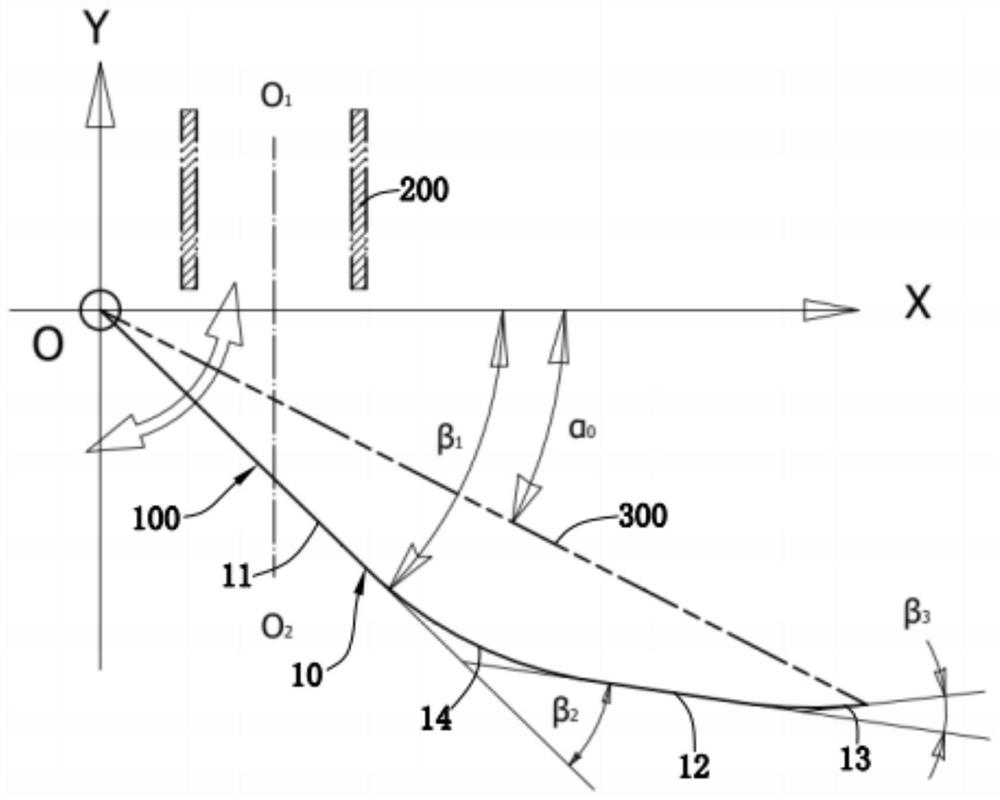
The invention provides a blast furnace material distribution folding chute. The blast furnace material distribution folding chute comprises a chute body with a material distribution cavity, the chute body comprises a first straight line section, a second straight line section and a tilting nozzle section, and the first straight line section is used for receiving materials falling from a central throat pipe; in the length direction of the chute body, the second straight line section is arranged at the discharging end of the first straight line section, and the second straight line section is obliquely arranged towards the inner side relative to the first straight line section; and in the length direction of the chute body, the tilting nozzle section is arranged at the end, away from the first straight line section, of the second straight line section, and the tilting nozzle section is obliquely arranged towards the inner side relative to the second straight line section. Meanwhile, the invention provides blast furnace material distribution equipment which comprises the blast furnace material distribution folding chute. Compared with the prior art, the blast furnace material distribution folding chute and the blast furnace material distribution equipment provided by the invention have the advantages that the material impact force and kinetic energy loss can be reduced, the material distribution quality is improved, and the wear-resistant life of the chute is prolonged.

Description

technical field [0001] The invention relates to the technical field of blast furnace material distribution, in particular to a blast furnace material distribution folding chute and blast furnace material distribution equipment. Background technique [0002] The blast furnace is the main equipment for iron and steel smelting, and the blast furnace distribution chute is the main distribution equipment on the blast furnace. Because the blast furnace distribution chute needs to distribute the materials forward and reverse around the center line of the blast furnace, its structure must be a symmetrical structure symmetrical to the section of the blast furnace axis. [0003] like figure 1 and figure 2 As shown in the prior art, the profile of the material chute structure on the symmetrical section of the blast furnace distribution chute 300 is a straight line. When the blast furnace distributes material from the center to the furnace wall, the amount of material distribution in...

Claims


Application Information

Patent Timeline
IPC IPC(8): C21B7/20
CPCC21B7/20
Inventor 刘峪箫黄雅彬刘利军于恒亮邱建红
Owner 湖南德尚源耐磨工业有限公司
Why Eureka
Try Eureka