
Solid rocket engine ignition device wire fixing combined mechanism

A technology for ignition devices and solid rockets, which is applied in the direction of rocket motor devices, machines/engines, jet propulsion devices, etc., can solve the problems that the environmental adaptability and reliability of ignition devices cannot be guaranteed, and the development and production of unfavorable missile models can be solved, so as to achieve improvement Environmental adaptability and working reliability, avoiding wire fatigue and aging, and eliminating the effects of damage modes

Active Publication Date: 2021-12-28
SHANGHAI XINLI POWER EQUIP RES INST
View PDF6 Cites 0 Cited by
  • Summary
  • Abstract
  • Description
  • Claims
  • Application Information

AI Technical Summary

Problems solved by technology

[0004]The wires of the existing solid rocket motor ignition devices are generally fixed by free throwing wires, without special fixing or connection. There are complex coupling environmental factors such as high-intensity shock, buffeting and transportation in the process of delivering the whole missile to the flight test. For example, if the ignition device wire is free to throw the wire, the environmental adaptability and reliability of the ignition device cannot be guaranteed. Therefore, this wire fixing method greatly increases the risk of failure, aging or damage of the ignition device wire, which is not conducive to the development and production of missile models

Method used

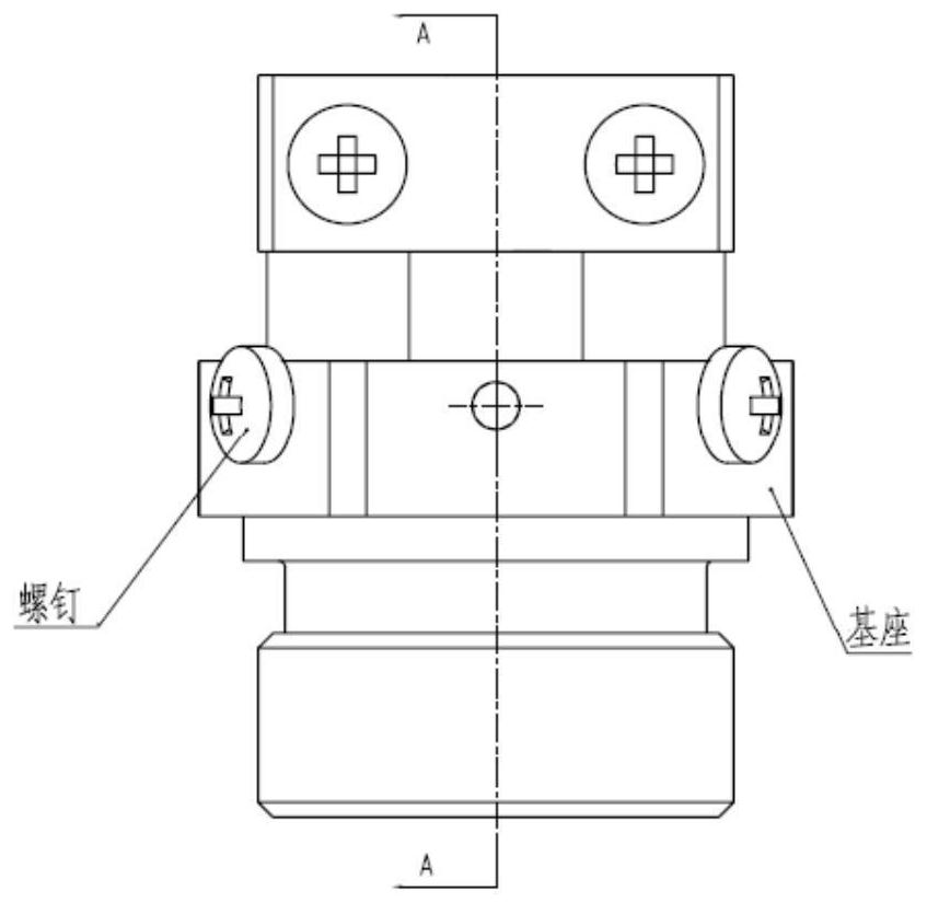
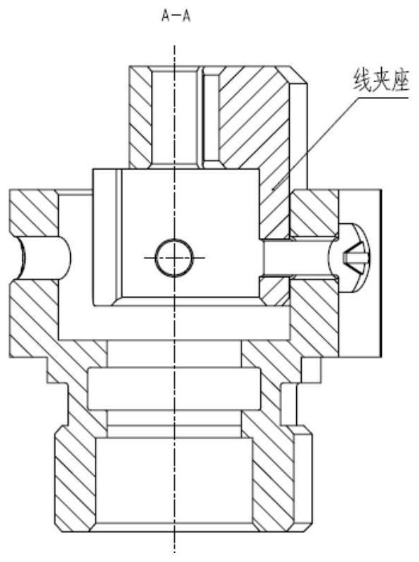
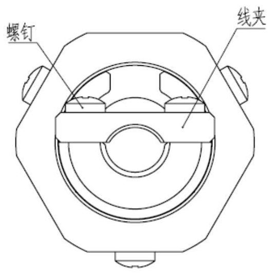

Image

  • Solid rocket engine ignition device wire fixing combined mechanism
  • Solid rocket engine ignition device wire fixing combined mechanism
  • Solid rocket engine ignition device wire fixing combined mechanism

Examples


Embodiment Construction

[0031] The invention will be described in more detail hereinafter with reference to the accompanying drawings showing embodiments of the invention. However, this invention may be embodied in many different forms and should not be construed as limited to the embodiments set forth herein. Rather, these embodiments are provided so that this disclosure will be thorough and complete, and will fully convey the scope of the invention to those skilled in the art. In these drawings, the size and relative sizes of layers and regions may be exaggerated for clarity.

[0032] figure 1 It is a schematic diagram of a solid rocket motor ignition device wire fixing combination mechanism of the present invention. The fixing wire combination mechanism has been applied in the development of a certain type of solid rocket motor, including: a base, a wire clamp seat, a wire clamp and a screw.

[0033] The base is made of TC4 titanium alloy metal material; the clamp seat and the clamp are both mad...


PUM


Abstract

The invention discloses a solid rocket engine ignition device wire fixing combined mechanism. The solid rocket engine ignition device wire fixing combined mechanism comprises a base, a wire clamp seat, a wire clamp and a screw, wherein the outer contour of the base body adopts a variable cross-section cylindrical threaded connection design structure, a hexahedron structure is designed at the top, six uniformly distributed through holes are designed in the same horizontal plane of the hexahedron structure, and a through channel is designed in the middle of the base body; the middle part of the wire clamp is provided with an arc-shaped groove for wiring of an ignition device wire, and two ends are provided with through holes; the wire clamp seat is of an open circular ring structure with steps, the bottom of the wire clamp seat is installed in a middle channel of the base body and connected with the base through a connecting screw, and the top of the wire clamp seat is connected with the wire clamp through a connecting screw; and after the ignition device wire penetrates through the middle channel of the base, radial pressing of the ignition device wire is achieved through the wire clamp seat, the wire clamp and the screw, and therefore effective and reliable fixing of the ignition device wire is achieved. The environment adaptability and the working reliability of the solid rocket engine ignition device of a certain model are improved.

Description

technical field [0001] The invention relates to the field of solid rocket motors, in particular to a solid rocket motor ignition device wire fixing combination mechanism. Background technique [0002] The ignition device is one of the important components in the solid rocket motor, and its reliability directly determines the success or failure of the missile launch mission. The ignition device is generally distributed at the head or tail of the solid rocket motor. The ignition device wire is a part of the ignition device. When the missile is launched, the ignition device wire is used as a signal transmission link to undertake the command of the missile control cabin and the engine cabin. Signal transmission, on the other hand, needs to provide a feedback signal transmission bridge for the computer on the missile to perform data interpretation after the solid rocket motor is working. [0003] The main structure of the ignition device wire is composed of multiple thin copper ...

Claims


Application Information

Patent Timeline
Patent Type & Authority Applications(China)
IPC IPC(8): F02K9/95H02G3/02
CPCF02K9/95H02G3/02
Inventor 刘道坤沈铁华陈昌将纪晓婷方常青孙晓娇余新乐薛牧遥刘乡芸
Owner SHANGHAI XINLI POWER EQUIP RES INST
Learn More