A tubular reactor serving as a combustor and heat exchanger

A pipeline reactor and pipeline technology, applied in heating tubes, indirect heat exchangers, heat exchanger types, etc., can solve the problems of insufficient heat transfer and insufficient heat for helium

Pending Publication Date: 2021-12-28
THERMOELEVATOR
View PDF5 Cites 0 Cited by
  • Summary
  • Abstract
  • Description
  • Claims
  • Application Information

AI Technical Summary

Problems solved by technology

Also, the radiation-limited other pipe surface is not hot

Method used


Image

  • A tubular reactor serving as a combustor and heat exchanger
  • A tubular reactor serving as a combustor and heat exchanger
  • A tubular reactor serving as a combustor and heat exchanger

Examples


Embodiment Construction

[0039] As will be appreciated by persons of ordinary skill in the art, various features of an embodiment shown and described with reference to any one figure may be combined with features shown in one or more other figures to produce not specifically defined Alternative embodiments shown or described. The combinations of features shown provide representative embodiments for typical applications. However, various combinations and modifications of the features consistent with the teachings of the present invention may be desired for particular applications or implementations. One of ordinary skill in the art may recognize similar applications or implementations, whether or not explicitly described or shown.

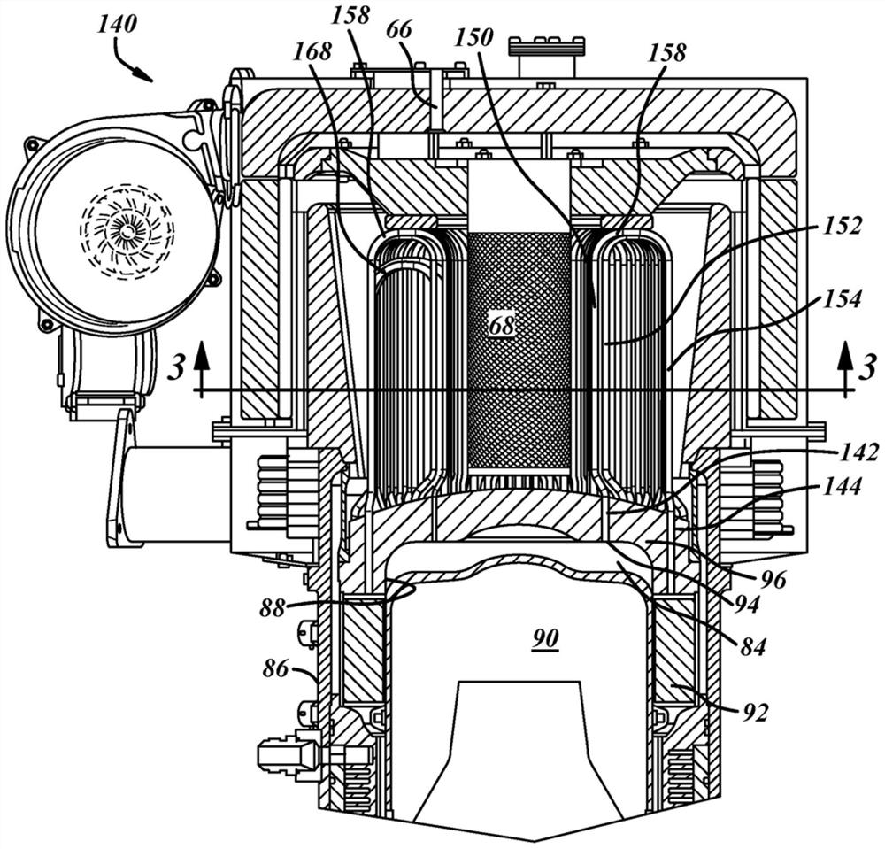
[0040] figure 2 An alternative combustion and heat exchange system is shown in . The upper portion of the heat pump 140 has a displacer 90 disposed in the cylinder 88 . The displacer 90 is coupled to the electromechanical system ( figure 2 not shown), similar to fig...


PUM


Abstract

A tubular reactor which acts as a combustor and heat exchanger is disclosed. Such reactor supplants a system with a combustor having a heat exchanger arranged around the combustor. The combined system includes a diffuser having an inlet for a fuel-and-air mixture and a plurality of holes defined in its surface through which the fuel-and-air mixture exits the diffuser and a plurality of tubes. First linear portions along the length of each tube are mutually parallel with a centerline of the first portions of the tubes displaced from the diffuser by a predetermined distance. Centerlines of the linear portions of adjacent tubes are displaced from each other by a predetermined gap. The fuel and air combust in the proximity of the first portion of the tubes for effective heat transfer to gases traveling through the tubes. Such a tubular reactor can be employed within a thermal-compression heat pump.

Description

technical field [0001] The invention relates to a pipeline reactor, which can be used for heat pumps, heat engines or other thermal devices. Background technique [0002] figure 1 One example of a thermal device, a compression-expansion heat pump 200 is shown. The heat pump 200 has a high-temperature heat exchanger 202 , a cylinder 204 and a cylinder 208 , the high-temperature displacer 206 reciprocates in the cylinder 204 , and the low-temperature displacer 210 reciprocates in the cylinder 208 . Electromechanical actuators in electromechanical section 220 are coupled to high temperature displacer 206 and low temperature displacer 210 and drive the displacers between ends of travel. A low molecular weight gas such as helium is contained in cylinders 204 and 208 and in the piping of high temperature heat exchanger 202 . There is a high temperature chamber 276 defined by a dome 278 , a cylinder wall 280 and the top surface of the displacer 206 . It also has a medium temper...

Claims


Application Information

Patent Timeline
IPC IPC(8): F25B30/02F25B9/14F02G1/055
CPCF25B30/02F25B9/14F02G1/055F02G2254/10F02G2255/10F28D7/08F02G1/044
Inventor P·霍夫鲍尔S·加迪拉朱A·贾达夫T·阿姆布里科
Owner THERMOELEVATOR
Why Eureka
Try Eureka