Antenna

An antenna and signal line technology, applied in the field of antennas, can solve problems such as shorter distances and difficulty in ensuring antenna performance

Pending Publication Date: 2021-12-28
AGC INC
View PDF2 Cites 0 Cited by
  • Summary
  • Abstract
  • Description
  • Claims
  • Application Information

AI Technical Summary

Problems solved by technology

[0004] However, in the prior art shown in Patent Document 1, when using a thin substrate such as a flexible substrate, the thickness of the dielectric is reduced and the distance from the radiation element to the ground conductor is relatively reduced. Short and difficult to secure the necessary antenna performance

Method used


Image

  • Antenna
  • Antenna
  • Antenna

Examples


Embodiment Construction

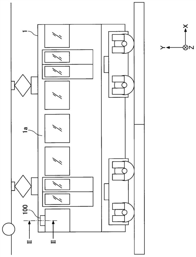
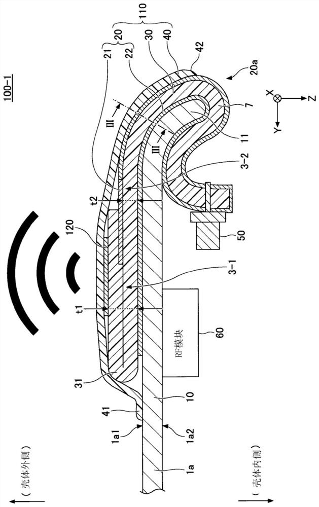
[0058] Hereinafter, embodiments according to the present invention will be described with reference to the drawings. In addition, in directions such as parallel, right angle, orthogonal, horizontal, vertical, up and down, and left and right, for example, when the housing in which the antenna is installed is formed of a curved surface, deviations to the extent that do not impair the effect of the present invention are allowed. In addition, the X-axis direction, the Y-axis direction, and the Z-axis direction represent directions parallel to the X-axis, directions parallel to the Y-axis, and directions parallel to the Z-axis, respectively. The X-axis direction, the Y-axis direction, and the Z-axis direction are orthogonal to each other. The XY plane, the YZ plane, and the ZX plane respectively represent a virtual plane parallel to the X-axis direction and the Y-axis direction, a virtual plane parallel to the Y-axis direction and the Z-axis direction, and a virtual plane parallel ...


PUM

PropertyMeasurementUnit
thicknessaaaaaaaaaa
thicknessaaaaaaaaaa
thicknessaaaaaaaaaa

Abstract

An antenna (100-1) is provided with: an antenna conductor (120) provided on the outside of a housing (1a); and a flexible substrate (30) comprising a first insulating portion (3-1) formed by folding a sheet-like dielectric body (7), a grounding conductor (22) provided between the first insulating portion (3-1) and the housing (1a), a second insulating portion (3-2) formed by the sheet-like dielectric body (7) where not folded, and a signal line (21) for feeding the antenna conductor (120). The first insulating portion (3-1) has a thickness greater than a thickness of the second insulating portion (3-2).

Description

technical field [0001] The present invention relates to antennas. Background technique [0002] It is known that antennas for transmitting and receiving various radio waves are mounted on robots, automobiles, trains, and the like. The vehicle-mounted planar antenna device disclosed in Patent Document 1 includes an antenna substrate, a radome for protecting the surface of the antenna substrate, a bracket for fixing the antenna substrate to a vehicle body, and a feed cable for feeding power to the antenna substrate. By stacking the ground conductor, the plate-like dielectric, and the radiation element facing the bracket in this arrangement, the antenna substrate is installed on the vehicle body. [0003] Patent Document 1: Japanese Patent Application Publication No. 5-55607 [0004] However, in the prior art shown in Patent Document 1, when using a thin substrate such as a flexible substrate, the thickness of the dielectric is reduced and the distance from the radiation elem...

Claims


Application Information

Patent Timeline
Patent Type & Authority Applications(China)
IPC IPC(8): H01Q1/22H01Q1/48H01Q1/32
CPCH01Q1/22H01Q1/48H01Q1/32H01Q1/38H01Q1/3291H01Q9/0457H01Q7/00H01Q9/16H05K1/0277H05K2201/10098
Inventor 森本康夫茂木健佐山稔贵小野元司加贺谷修
Owner AGC INC
Why Eureka
Try Eureka