Wireless blood pressure continuous monitoring system based on PWTT

A monitoring system and blood pressure technology, which is applied in vascular assessment, telemetry patient monitoring, diagnostic recording/measurement, etc., can solve the problems of fixed function, weak expandability, inconvenient putting on and taking off, etc., and achieves limited measurement position and low cost Low, easy on and off effect

Pending Publication Date: 2021-12-31
NANJING UNIV
0 Cites 2 Cited by

AI-Extracted Technical Summary

Problems solved by technology

[0004] The disadvantage of the current PWTT-based blood pressure monitoring device is that the monitoring system is not wearable and expandable
The sensors in different parts are connected to a main board or between multiple modules through long wires, which is inconvenient to pu...

Method used

In the beacon network, the acquisition process of two terminal main circuit modules is controlled by appropriate delay function duration, after the test, the average time error between the two from parsing the beacon frame to issuing the acquisition command is controlled at About 38us. The beacon network of the Zigbee system specifies the structure of the superframe. The active area of ​​the superframe is divided into 16 equal-length time slots GTS. After the time slot, data transmission is only performed in a specific time slot, so as to avoid data rush-in and loss caused by different terminals using contention access mode to transmit data.
[0030] Pulse main circuit block diagram, as shown in Figure 3, including MCU module, photoelectric pulse detection module, power management module and wireless transmission module. The MCU module adopts the MSP430F5528 microcontr...

Abstract

The invention provides a wireless blood pressure continuous monitoring system based on PWTT. The system comprises a coordinator, a wearable electrocardio chest strap terminal, a wearable pulse wrist strap terminal and an upper computer, and is characterized in that the coordinator establishes a sensor network based on a Zigbee protocol; the wearable electrocardio chest strap terminal and the wearable pulse wrist strap terminal respectively collect electrocardio ECG signals and pulse PPG signals of a human body, receive and analyze periodically sent beacon frames, and complete synchronous collection of the ECG signals and the PPG signals of the two terminals; and the upper computer performs signal preprocessing such as amplitude conversion and filtering on the ECG signals and the PPG signals, and the functions of waveform display, blood pressure calculation and data storage are completed. Based on a PWTT blood pressure measurement principle, in combination with networking of a wireless transmission technology and a synchronization technology, synchronous collection of the ECG signals and the PPG signals is completed, constraint of an inflatable cuff and a traditional wire is eliminated, wireless blood pressure continuous monitoring based on PWTT is achieved, and the wireless blood pressure continuous monitoring system has the remarkable advantages of being extensible, wearable, low in cost, portable and the like.

Application Domain

Evaluation of blood vesselsSensors +2

Technology Topic

Medical emergencyBiomedical engineering +7

Image

  • Wireless blood pressure continuous monitoring system based on PWTT
  • Wireless blood pressure continuous monitoring system based on PWTT
  • Wireless blood pressure continuous monitoring system based on PWTT

Examples

  • Experimental program(1)

Example Embodiment

[0025] In order to make the technical solution proposed by the present invention clearer, the present invention will be described and introduced in detail below in conjunction with the accompanying drawings and specific embodiments, but the following embodiments are only illustrative, not restrictive.
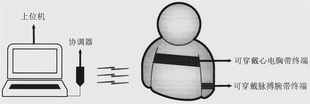
[0026] A wireless blood pressure monitoring system based on PWTT, see appendix figure 1 , including a coordinator, a wearable ECG chest strap terminal, a wearable pulse wristband terminal and a host computer; the coordinator is responsible for setting up a sensor network and controlling the synchronous collection and transmission of terminal data; the wearable ECG chest strap terminal, Responsible for the collection of ECG signals and wireless transmission to the coordinator, including the ECG main circuit module, ECG housing, and chest strap; the wearable pulse wristband terminal is responsible for the collection of PPG signals and wireless transmission to the coordinator, including the pulse Main circuit module, pulse housing and wristband; after the host computer receives the data sent by the coordinator, it performs preprocessing of the ECG signal and the PPG signal, and displays the filtered waveform and blood pressure detection results in real time; the coordinator The device, wearable ECG chest strap terminal, and wearable pulse wristband terminal build a network according to the IEEE802.15.4 standard. Based on the TIMAC protocol stack, the beacon network is set up, serial data is sent and received, and the terminal synchronously collects signals and other functions.
[0027] For the block diagram of the coordinator, see the attached figure 2, including wireless transmission module, power management module and serial port conversion module. Among them, the wireless transmission module adopts TI's CC2530 series, based on the IEEE802.15.4 standard Zigbee module to establish a beacon-enabled sensor network, trigger the serial port interrupt service function through the button interrupt, scan the channel in the interrupt service function and select the appropriate channel Build a network, set the extended address, short address, and Beacon frame attributes of the coordinator to set the MAC layer parameters, enable the beacon network, and periodically send beacon frames after the network is successfully established. The serial port module adopts CH340 conversion chip, and the terminal data received by the coordinator can realize data compatibility and transmit to the host computer through the conversion chip.
[0028] Block diagram of ECG main circuit module, as attached image 3 As shown, it includes ECG electrode A, ECG electrode B, MCU module, ECG detection module, power management module and wireless transmission module. Among them, the MCU module adopts MSP430F5528 microcontroller of TI Company, which is mainly responsible for controlling the data acquisition and data transmission of the ECG detection module, and data transmission with the wireless transmission module. ECG electrode A and ECG electrode B use disposable medical electrodes to touch the skin to obtain human ECG signals, and are connected to the ECG detection module through wires. The ECG detection module uses ADS1298 model high-precision biological analog front-end to convert ECG signals into digital signals , set the sampling rate of 250sps, the internal gain is 12, the data is transmitted to the MCU module through the SPI bus, and the wireless transmission module uses the CC2530 microprocessor to complete the functions of terminal network access, beacon frame analysis and data wireless transmission.
[0029] The wearable ECG chest belt terminal is powered on and initialized, completes the system clock setting, serial port setting, and initializing the ADS1298 module. Receive the beacon frame sent by the coordinator, analyze the beacon load to trigger the local acquisition task, start the ADS1298 data conversion and enable the interrupt, ADS1298 completes a conversion every 4ms, and transmits data with the MCU module through SPI communication. After receiving the converted data from ADS1298, the MCU module packs the data and sends it to the wireless transmission module through the serial port. After receiving the data transmitted by the serial port, the wireless transmission module triggers the serial port interruption time, encapsulates the data frame into a MAC layer message, and transmits it wirelessly to the coordinator.
[0030] The block diagram of the pulse main circuit module, as attached image 3 As shown, it includes MCU module, photoelectric pulse detection module, power management module and wireless transmission module. The MCU module adopts the MSP430F5528 microcontroller of TI Company, which contains a 12-bit ADC analog-to-digital conversion module, which performs analog-to-digital conversion on the PPG at a sampling rate of 250Hz, and transmits the data to the wireless transmission module. The photoelectric pulse detection module includes a photoelectric sensor, a filter amplifier circuit, and a level-up circuit. The photoelectric sensor is an NJL5310R surface-mounted photosensor, which is equipped with an LED light-emitting diode with a wavelength of 525nm and a high-sensitivity photodiode to detect the pulse at the wrist. PPG signal. The filter amplifier circuit performs noise reduction and amplification on the PPG signal to improve the signal-to-noise ratio. The wireless transmission module uses a CC2530 microprocessor to complete functions such as networking requests, beacon frame analysis, and data wireless transmission.
[0031] The wearable pulse wristband terminal is powered on and initialized, completes the system clock setting, serial port setting, ADC module basic parameter setting and other steps, waits for the coordinator to network successfully, presses the networking button to trigger the serial port interrupt, and sends a network access request. After the network is successfully connected Regularly receive the beacon frame sent by the coordinator, analyze the beacon load to trigger the local acquisition task, enable the internal ADC interrupt, and set the ADC internal sampling rate to 250Hz. The MCU packs the data converted by the ADC module and sends it to the wireless transmission module through the serial port. After receiving the data transmitted by the serial port, the wireless transmission module triggers the serial port interruption time, encapsulates the data frame into a MAC layer message, and wirelessly transmits it to the coordinator.
[0032] In the beacon network, the acquisition process of the two terminal main circuit modules is controlled by an appropriate delay function. After testing, the average time error between the two from parsing the beacon frame to issuing the acquisition command is controlled at about 38us. The beacon network of the Zigbee system specifies the structure of the superframe. The active area of ​​the superframe is divided into 16 equal-length time slots GTS. After the time slot, data transmission is only performed in a specific time slot, so as to avoid data rush-in and loss caused by different terminals using contention access mode to transmit data.
[0033] In the beacon network, the wearable ECG chest strap terminal collects human ECG signals, and the wearable pulse wristband collects PPG signals. Different terminals access the channel in a time-division multiplexing manner. The coordinator converts the data through the serial port after receiving the data transmitted by the terminal. The module sends data to the host computer.
[0034] The upper computer has the functions of signal preprocessing, display, calculation and storage, and is responsible for performing amplitude conversion and filtering processing on the ECG and PPG signals transmitted by the coordinator, and selecting the R wave peak value of the ECG signal and the PPG signal wave peak value as feature points to calculate the ECG signal. The characteristic point time difference between the PPG signal and the PPG signal is the pulse transit time PWTT, and the calculated value is substituted into the blood pressure estimation equation to obtain the estimated value of blood pressure. Among them, BP in the blood pressure estimation equation can be systolic blood pressure SBP or diastolic blood pressure DBP, and the parameters of the two sets of equations are obtained by fitting the test data of ten volunteers: a=110.3, k=-0.176 and a=70.86, k= -0.095, the estimation equation of systolic blood pressure is SBP=110.3-0.176*PWTT, and the estimation equation of diastolic blood pressure is DBP=70.86-0.095*PWTT. Substituting the real-time calculated PWTT value into the equation can estimate SBP and DBP. The upper computer completes the real-time display of the detected ECG and PPG waveforms and gives the calculation results of systolic and diastolic blood pressure, see the attached Figure 5.
[0035] Based on the signals collected synchronously by the wireless continuous blood pressure monitoring system, vital signs such as respiration, heart rate, and heart rate variability can be further monitored in real time, which can be expanded as needed.
[0036] It should be noted that the above-mentioned embodiments are not used to limit the protection scope of the present invention, and equivalent transformations or replacements made on the basis of the above-mentioned technical solutions all fall within the protection scope of the claims of the present invention.

PUM

no PUM

Description & Claims & Application Information

We can also present the details of the Description, Claims and Application information to help users get a comprehensive understanding of the technical details of the patent, such as background art, summary of invention, brief description of drawings, description of embodiments, and other original content. On the other hand, users can also determine the specific scope of protection of the technology through the list of claims; as well as understand the changes in the life cycle of the technology with the presentation of the patent timeline. Login to view more.

Similar technology patents

Apparatus and method for low-density cellular wood plastic composites

InactiveUS20050067729A1less-expensivelow cost
Owner:STRANDEX CORP

Haptic trackball device

InactiveUS7710399B2simple actuatorlow cost
Owner:IMMERSION CORPORATION

Steering Arrangement for a Trailer

InactiveUS20110018231A1low cost
Owner:ZF FRIEDRICHSHAFEN AG

Classification and recommendation of technical efficacy words

  • low cost

System and method for transmitting wireless digital service signals via power transmission lines

ActiveUS7929940B1reduce bandwidth requirementlow cost
Owner:NEXTEL COMMUNICATIONS

System and method for determination of position

InactiveUS20090149202A1low costreduce requirement
Owner:STEELE CHRISTIAN

Adaptive antenna optimization network

InactiveUS6961368B2low costminimal space
Owner:ERICSSON INC

Antenna device and method for attaching the same

ActiveUS20150138022A1low costimproved strength characteristic
Owner:NEC CORP
Why Eureka
Try Eureka