Steel core, ceramic roller and roller table

A technology of steel core and ceramic sleeve, applied in the direction of roller table, roller column, conveyor objects, etc., can solve problems such as breakage, and achieve the effect of ensuring normal rotation

Pending Publication Date: 2021-12-31
深圳南玻科技有限公司 +1
View PDF14 Cites 0 Cited by
  • Summary
  • Abstract
  • Description
  • Claims
  • Application Information

AI Technical Summary

Problems solved by technology

Due to the high temperature of the working environment of the ceramic roller, the glued silica gel softens, causing the ceramic sleeve to stop rotating, resulting in accidents such as breakage of the items on the ceramic sleeve.

Method used


Image

  • Steel core, ceramic roller and roller table
  • Steel core, ceramic roller and roller table
  • Steel core, ceramic roller and roller table

Examples


Embodiment Construction

[0040] Embodiments of the present invention are described in detail below, examples of which are shown in the drawings, wherein the same or similar reference numerals designate the same or similar elements or elements having the same or similar functions throughout. The embodiments described below by referring to the figures are exemplary only for explaining the present invention and should not be construed as limiting the present invention.

[0041] In the description of the present invention, it should be understood that the orientation descriptions, such as up, down, front, back, left, right, etc. indicated orientations or positional relationships are based on the orientations or positional relationships shown in the drawings, and are only In order to facilitate the description of the present invention and simplify the description, it does not indicate or imply that the device or element referred to must have a specific orientation, be constructed and operated in a specific ...


PUM


Abstract

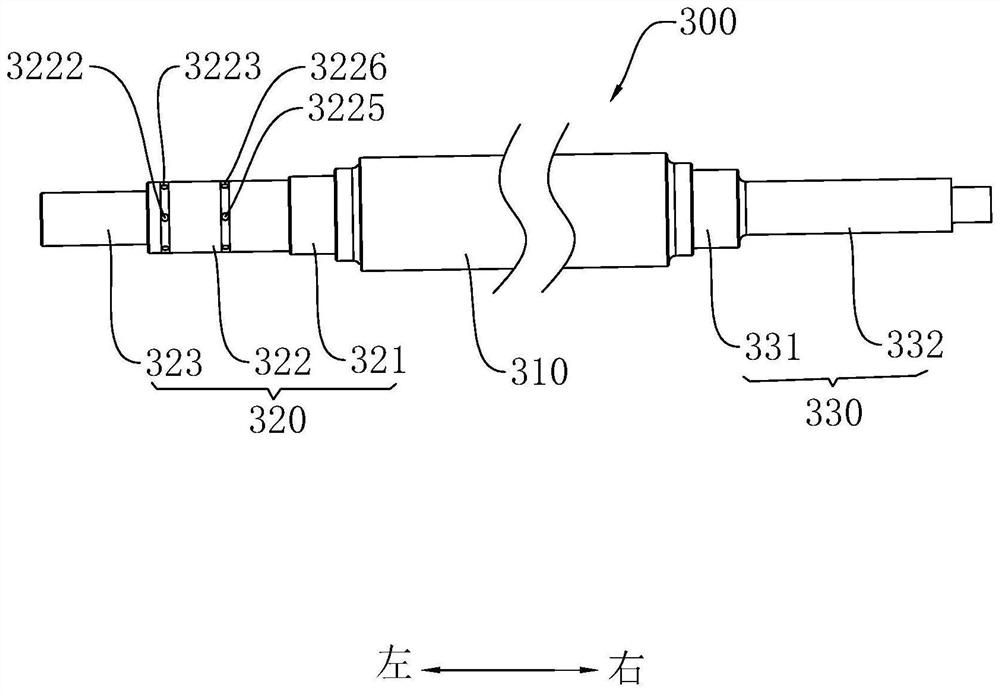
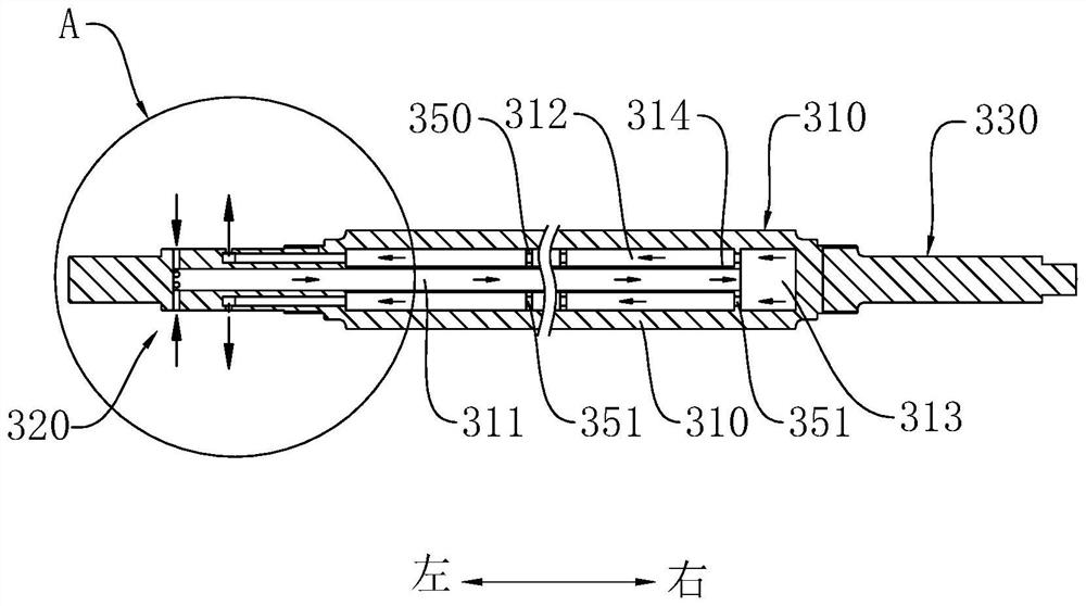
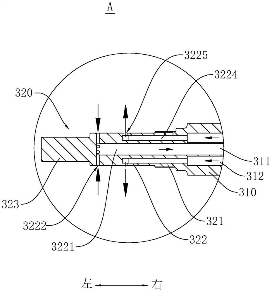
The invention discloses a steel core, a ceramic roller and a roller table. The steel core sequentially comprises a first mounting section, a cooling section and a second mounting section in the axial direction of the steel core. A center shaft cooling inner cavity and an annular cooling outer cavity are formed in the cooling section in the axial direction of the cooling section, the center axis of the center shaft cooling inner cavity and the center axis of the annular cooling outer cavity coincide with the center axis of the steel core, and the end, away from the first mounting section, of the center shaft cooling inner cavity communicates with the end, away from the second mounting section, of the annular cooling outer cavity; and the first installation section is provided with a water inlet conveying channel and a water outlet conveying channel. When the ceramic roller works in a high-temperature environment, due to the fact that the steel core can cool the ceramic sleeve, adhesion silica gel at the end of the ceramic sleeve is prevented from being softened, normal rotation of the ceramic sleeve is guaranteed, and products outside the ceramic sleeve can be safely conveyed.

Description

technical field [0001] The invention relates to the technical field of ceramic rollers, in particular, a steel core, a ceramic roller and a roller table are designed. Background technique [0002] In the related art, the ceramic roller includes a frame, a steel shaft head, a ceramic sleeve and a silicone rubber. The two steel shaft heads are rotatably mounted on the frame and set opposite to each other. The ceramic sleeve is fitted and connected between the two steel shaft heads. , the dipped silica gel is located between the end of the ceramic sleeve and the steel shaft head, so that the ceramic sleeve and the steel shaft head are fixedly connected. Due to the high temperature of the working environment of the ceramic roller, the glued silica gel is softened, causing the ceramic sleeve to stop rotating, thereby causing accidents such as breakage of the articles on the ceramic sleeve. Contents of the invention [0003] The present invention aims to solve at least one of t...

Claims


Application Information

Patent Timeline
IPC IPC(8): B65G49/06B65G39/02B65G39/07B65G13/00F25D1/02
CPCB65G49/064B65G39/02B65G39/07B65G13/00F25D1/02
Inventor 李红香孙恒裕杨国伟曾智武田元中邱声夫刘建党陈志鴻何进
Owner 深圳南玻科技有限公司
Why Eureka
Try Eureka