Electric horizontal rolled clamp and using method thereof

A horizontal roll and clamp technology, applied in the field of hoisting equipment, can solve the problems of increasing the opening stroke distance of the electric clamp arm, collision or scratching of the electric horizontal roll clamp, and restriction of production rhythm, so as to reduce the impact of the jaws on steel The phenomenon of the upper end of the coil, the effect of preventing the claws from scratching the inner wall of the steel coil, good economic benefits and social effects

Pending Publication Date: 2021-12-31
安徽马钢和菱实业有限公司
View PDF0 Cites 1 Cited by
  • Summary
  • Abstract
  • Description
  • Claims
  • Application Information

AI Technical Summary

Problems solved by technology

For a long time, in the process of hoisting, electric horizontal coil clamps often collide or scratch the steel coil, causing appearance damage, causing quality objections, resulting in a decline in product yield and an increase in cost
Through on-site observation and analysis, the direct cause of the damage to the steel coil is the descending stage of the hoisting steel wire rope of the crane hoisting the electric horizontal coil tongs to lift the steel coils through the hook group and the contact with the steel coils after the electric horizontal coil tongs are hoisted. In the rising stage after separation, although the two arms of the electric horizontal coil tongs are in the open state, the claws on the arms are very easy to collide with or scratch the steel coil
Further analysis, the main reason is that although the distance between the two claws is about 200mm-300mm larger than the width of the steel coil, the distance between the claws and the end face of the steel coil is about 100mm-150mm under the ideal centering state. In practice, in the fast-paced During the production process, when lifting, the visual error of the operation and the skill level affect the control accuracy of the crane and the electric clamp, and the stability of the electric clamp under the traction of the wire rope is not good, etc., resulting in the electric horizontal roll clamp. The neutral deviation between the clamp and the steel coil is often greater than 150mm, so the distance between the jaws and the steel coil cannot fully meet the requirements of the neutral error between the electric horizontal coil clamp and the steel coil
If the transformation increases the opening stroke distance of the electric clamp arm, then firstly, it will restrict the production rhythm and reduce production efficiency; secondly, the electric horizontal coil clamp will collide due to the increase in width when hoisting in the storage area where steel coils are arranged vertically and horizontally. Other steel coils; in addition, when the electric horizontal coil tongs lift the hot-rolled steel coils off the assembly line and put them into storage, they are generally in a high-temperature environment, so that the equipment with electronic control devices installed in the jaw area cannot be used normally in this environment

Method used


Image

  • Electric horizontal rolled clamp and using method thereof
  • Electric horizontal rolled clamp and using method thereof
  • Electric horizontal rolled clamp and using method thereof

Examples


Embodiment Construction

[0044] The technical solutions in the embodiments of the invention will be clearly and completely described below in conjunction with the accompanying drawings in the embodiments of the invention. Obviously, the described embodiments are only some, not all, embodiments of the invention. Based on the embodiments of the present invention, all other embodiments obtained by persons of ordinary skill in the art without making creative efforts belong to the protection scope of the present invention.

[0045] Unless otherwise defined, the technical terms or scientific terms used herein shall have the usual meanings understood by those having ordinary skill in the art to which the present disclosure belongs. "Up", "Down", "Left", "Right", "Inner", "Outer", "Front", "Back", etc. used in the specification and claims of this patent application are only used to indicate relative positions When the absolute position of the described object changes, the relative positional relationship also...


PUM


Abstract

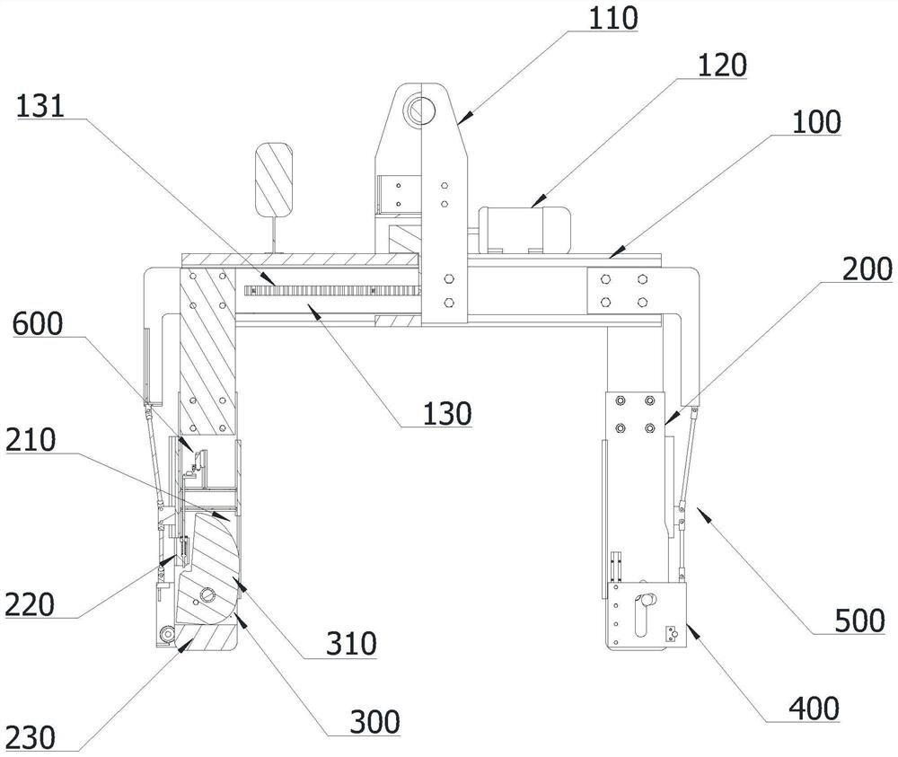
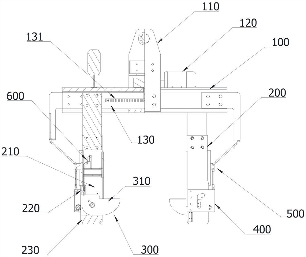
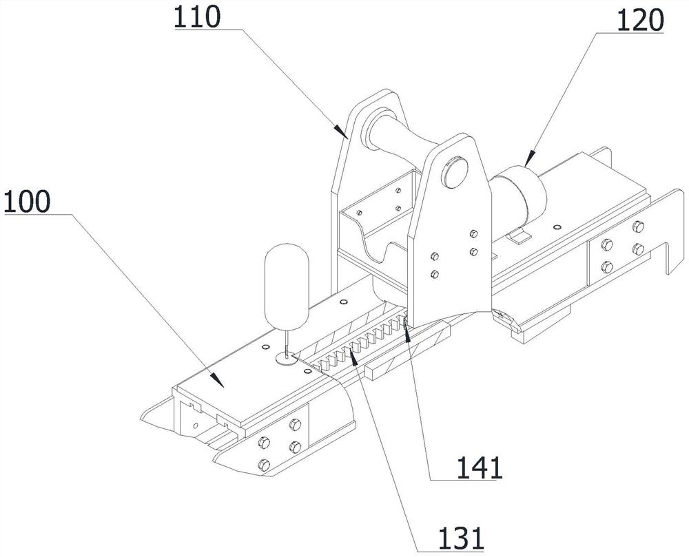
The invention discloses an electric horizontal rolled clamp and a using method thereof. The electric horizontal rolled clamp comprises a hanging beam, a hanging shaft device is arranged in the middle of the hanging beam, clamp arms are arranged on the two sides of the lower portion of the hanging beam correspondingly, a gear motor is arranged on the upper surface of the hanging beam, the bottom of the hanging beam is open, telescopic beams are arranged on the front side and the rear side inside the hanging beam correspondingly, a rack is transversely arranged on the inner side surface of each telescopic beam, the output end of the gear motor is connected to a transmission mechanism, the transmission mechanism comprises an output shaft, a gear meshing with the two racks at the same time is installed at the end part of the output shaft, each clamp arm is fixedly connected to one telescopic beam, the whole clamp arm is of a long-strip-shaped frame structure, a rectangular opening is formed in the lower portion of each clamp arm, a clamp claw assembly is movably arranged in the opening, guide frames capable of moving up and down on the outer sides of the clamp arms are arranged on the outer sides of the clamp arms, and guide rail connecting rod mechanisms are movably arranged between the guide frames and the corresponding ends of the hanging beam. By means of the electric horizontal rolled clamp, the problem that the electric horizontal rolled clamp collides or rubs steel coils can be effectively solved, the steel coil yield is increased, the equipment failure rate is reduced, and the equipment maintenance cost is reduced.

Description

technical field [0001] The invention relates to the technical field of hoisting equipment, in particular to an electric horizontal roll tong and a using method thereof. Background technique [0002] In iron and steel enterprises, the off-line warehousing and outbound operations of steel coils are all realized by the crane by controlling the electric horizontal coil clamps suspended on the hook. For a long time, in the process of lifting operations, electric horizontal coil tongs often collide or scratch the steel coil, causing appearance damage, causing quality objections, resulting in a decline in product yield and an increase in cost. Through on-site observation and analysis, the direct cause of the damage to the steel coil is the descending stage of the hoisting steel wire rope of the crane hoisting the electric horizontal coil tongs to lift the steel coils through the hook group and the contact with the steel coils after the electric horizontal coil tongs are hoisted. I...

Claims


Application Information

Patent Timeline
Patent Type & Authority Applications(China)
IPC IPC(8): B66C1/30
CPCB66C1/30
Inventor 陈爱民范雷震魏刚姜伟宏王弦王宏元郑军陈祥
Owner 安徽马钢和菱实业有限公司
Why Eureka
Try Eureka