Optical signal processor, radar, and optical signal processing method
A technology of optical signal and processor, applied in the field of optical signal processing, which can solve the problems of optical signal fluctuations and the detection device being unable to determine whether to receive reflected optical signals, etc.
- Summary
- Abstract
- Description
- Claims
- Application Information
AI Technical Summary
Problems solved by technology
Method used
Image
Examples
Embodiment 1
[0098] The application scenario of the optical signal processor provided by the embodiment of the present application is firstly described as an example below.
[0099] For example, the optical signal processor of the embodiment of the present application can be applied to the technical field of laser-based radar detection.
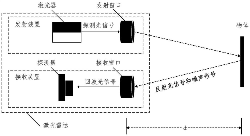
[0100] Figure 1A It is a schematic diagram 1 of the application scenario involved in the embodiment of this application. Such as Figure 1A As shown, in the embodiment of the present application, the lidar may include a transmitting device and a receiving device.
[0101] For example, the emitting device may be used to emit a probe light signal. Wherein, the detection light signal can be used to detect whether there is an object in the target area and to obtain information of the detected object. In an example, the transmitting device may be a laser, and the laser transmits the detection light signal to the target area through the transmission window, ...
Embodiment 2
[0152] The composition and structure of the optical signal processor provided in the embodiment of the present application will be exemplarily described below.
[0153] Figure 4 Schematic diagram 1 of the structure of the optical signal processor provided by the embodiment of the present application.
[0154] Such as Figure 4 shown in figure 2 On the basis of the optical signal processor shown, the signal beam splitting component 100 in the optical signal processor 1000 of the embodiment of the present application may include a dichroic prism 111 and a reflective prism 112, a first filter 121, a notch 122, a second Two filters 131.
[0155] Wherein, the dichroic prism 111 is used to receive the echo light signal, and output the echo light signal to the reflective prism and the second filter respectively; the reflective prism 112 is used to reflect the received echo light signal to the first filter.
[0156] The first optical filter 121 is used to filter the received ec...
Embodiment 3
[0182] The embodiment of the present application also provides an optical signal processor.
[0183] Figure 7 Schematic diagram of the structure of the optical signal processor provided for the embodiment of this application Figure II . Such as Figure 7 shown in figure 2 On the basis of the optical signal processor shown, the signal beam splitting component 100 in the optical signal processor 1000 of the embodiment of the present application may include a fiber beam splitter 113, a first optical filter 121, a notch filter 122, a second filter Light sheet 131.
[0184] Wherein, the optical fiber beam splitter 113 is configured to receive the echo optical signal, and output the echo optical signal to the first filter 121 and the second filter 131 respectively through an optical fiber.
[0185] The first optical filter 121 is used to filter the received echo optical signal, and output the echo optical signal in the signal extraction band to the notch filter; the notch fi...
PUM
 Abstract
Description
Claims
Application Information
 - R&D
- Intellectual Property
- Life Sciences
- Materials
- Tech Scout
- Unparalleled Data Quality
- Higher Quality Content
- 60% Fewer Hallucinations
Browse by: Latest US Patents, China's latest patents, Technical Efficacy Thesaurus, Application Domain, Technology Topic, Popular Technical Reports.
© 2025 PatSnap. All rights reserved.Legal|Privacy policy|Modern Slavery Act Transparency Statement|Sitemap|About US| Contact US: help@patsnap.com


