Driving control circuit, control method of driving control circuit and life electric appliance
A technology for driving control circuits and driving circuits, which is applied in the field of driving control circuits and household electrical appliances, and can solve problems such as unsatisfactory control requirements and undetermined operating status
- Summary
- Abstract
- Description
- Claims
- Application Information
AI Technical Summary
Problems solved by technology
Method used
Image

Examples
Embodiment 1
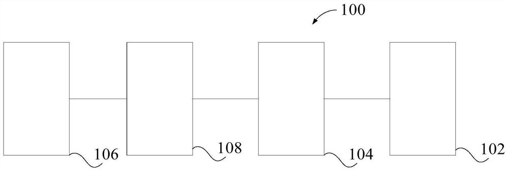
[0051] In one embodiment of the present invention, as figure 1 , figure 2 with image 3 As shown, a drive control circuit 100 is provided for an ultrasonic transducer 122, including: a drive circuit 102, a first detection circuit 104, a second detection circuit 106 and a controller 108, wherein the drive circuit 102 is configured as Drive the ultrasonic transducer 122; the first detection circuit 104 is connected to the drive circuit 102; the second detection circuit 106 is connected to the power supply circuit of the drive control circuit 100, and the second detection circuit 106 is configured to obtain the zero-crossing signal of the power supply circuit The controller 108 is connected to the first detection circuit 104 and the second detection circuit 106, and the controller 108 is configured to: receive the zero-crossing signal of the power supply circuit, and control the first detection circuit 104 to detect the driving circuit 102 within the first duration The number ...
Embodiment 2
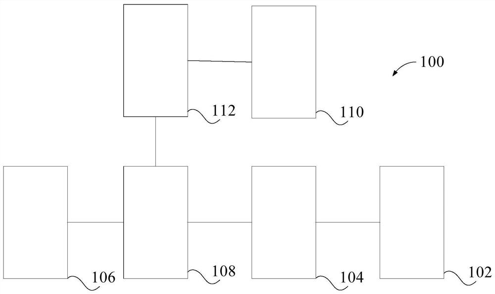
[0055] In the above example, if figure 2 As shown, the drive control circuit 100 further includes an inverter circuit 110, the inverter circuit 110 includes a first switching device Q1 and a second switching device Q2, the first end of the second switching device Q2 is connected to the second end of the first switching device Q1 connected; the drive circuit 102 includes a first transformer T1, wherein the primary coil of the first transformer T1 is connected in series in the loop where the resonant circuit 120 of the ultrasonic transducer 122 is located, and the first secondary coil of the first transformer T1 is connected in series. One end is connected to the control end of the first switching device Q1, the second end of the first secondary coil of the first transformer T1 is connected to the second end of the second switching device Q2; the second secondary coil of the first transformer T1 The first end of the coil is connected to the control end of the second switching d...
Embodiment 3
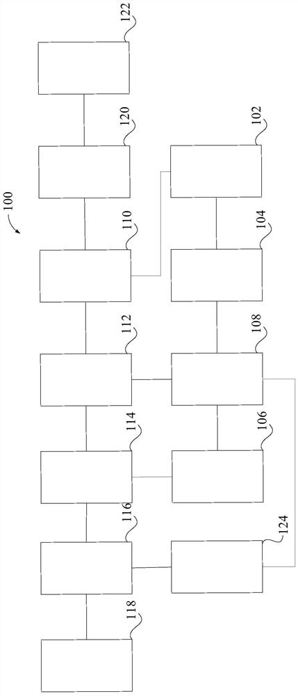
[0061] In any of the above embodiments, if figure 2 with image 3As shown, the drive control circuit 100 further includes: a switch circuit 112, and the switch circuit 112 includes: a third switch device Q3, the first terminal of the third switch device Q3 receives the first power supply signal, and the control terminal of the third switch device Q3 is connected to the control terminal The output end of the device 108 is connected; the third capacitor C3, the first end of the third capacitor C3 is connected to the second end of the third switching device Q3, and the second end of the third capacitor C3 is grounded; the fourth switching device Q4, The first terminal of the fourth switching device Q4 is connected to the first terminal of the third capacitor C3, the second terminal of the fourth switching device Q4 is connected to the second terminal of the third capacitor C3, and the third terminal of the fourth switching device Q4 is connected to the second terminal of the thi...
PUM
 Abstract
Description
Claims
Application Information
 - R&D
- Intellectual Property
- Life Sciences
- Materials
- Tech Scout
- Unparalleled Data Quality
- Higher Quality Content
- 60% Fewer Hallucinations
Browse by: Latest US Patents, China's latest patents, Technical Efficacy Thesaurus, Application Domain, Technology Topic, Popular Technical Reports.
© 2025 PatSnap. All rights reserved.Legal|Privacy policy|Modern Slavery Act Transparency Statement|Sitemap|About US| Contact US: help@patsnap.com