Method for determining maximum reactive capacity of MMC type direct-current ice melting device

A technology of DC ice melting and maximum reactive power, applied in reactive power compensation, reactive power adjustment/elimination/compensation, overhead installation, etc., can solve the problems that cannot be calculated, have many parameters, and do not reasonably and effectively satisfy the coupling of internal and external parameters relationship and other issues to achieve the effect of improving equipment availability

Pending Publication Date: 2021-12-31
GUIZHOU POWER GRID CO LTD
View PDF0 Cites 0 Cited by
  • Summary
  • Abstract
  • Description
  • Claims
  • Application Information

AI Technical Summary

Problems solved by technology

[0003] The technical problem to be solved by the present invention is to provide a method for determining the maximum reactive capacity of the MMC-type DC ice-melting device, so as to solve the problem that the MMC-type ice-melting device has many parameters in the prior art and does not satisfy the internal and external parameters reasonably and effectively. The coupling relationship of the MMC type DC ice-melting device is not fully utilized. The characteristics of the decoupling control of active power and reactive power of the MMC type DC ice-melting device are not fully utilized, so technical problems such as the maximum reactive power capacity under the conditions of ice-melting conditions cannot be calculated.

Method used


Image

  • Method for determining maximum reactive capacity of MMC type direct-current ice melting device
  • Method for determining maximum reactive capacity of MMC type direct-current ice melting device
  • Method for determining maximum reactive capacity of MMC type direct-current ice melting device

Examples


Embodiment Construction

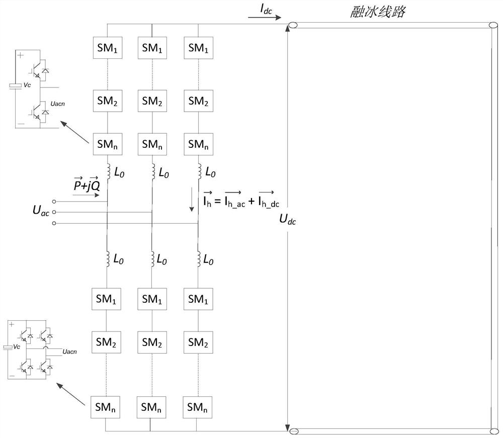
[0034] A method for determining the maximum reactive capacity of an MMC type DC deicing device, used to determine the active capacity and maximum reactive capacity of an MMC type DC deicing device according to engineering requirements, determine the PQ circle for device operation, and set the required The DC resistance value of the ice-melting line is R, and the DC ice-melting current of the line is I dc , the DC ice-melting voltage is U dc , the AC system line voltage is U ac , the steps to determine the capacity of the MMC DC ice-melting device are as follows:

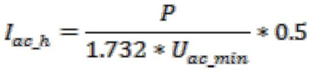
[0035] S1: According to the DC resistance value R and the 1-1, 1-2 wiring mode of the deicing wiring, calculate the equivalent deicing resistance R eq , according to the line DC ice melting current I dc , calculate the required active capacity as The required DC ice-melting voltage is U dc = I dc *R eq ;

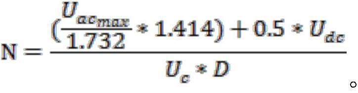
[0036] S2: according to the AC side line voltage U of the ice melting device ac and its fluctuation ra...


PUM


Abstract

The invention discloses a method for determining the maximum reactive capacity of an MMC type direct-current ice melting device, and the method comprises the following steps of calculating equivalent ice melting resistance according to a direct-current resistance value, and calculating the required active capacity and direct-current ice melting voltage according to the direct-current ice melting current of a line; calculating the number of required bridge arm modules according to the alternating-current side line voltage and fluctuation range of the ice melting device, the direct-current ice melting voltage, the module direct-current operation voltage and the module maximum modulation ratio; calculating a bridge arm current AC component, a bridge arm current DC component and a bridge arm current effective value according to the AC side line voltage; calculating the capacitance of a single module according to the number of the bridge arm modules and the active power; according to the effective current of the bridge arm, regarding the MMC device as two sets of parallel reactive power compensation devices to calculate reactive capacity in a reactive power operation mode; determining module capacity corresponding to the reactive capacity and carrying out accounting to obtain module capacitance; and finally determining the maximum reactive capacitance. The technical problem that the maximum reactive capacity under the ice melting working condition cannot be calculated is solved.

Description

technical field [0001] The invention belongs to the field of high-power electric electronic equipment, and in particular relates to a method for determining the maximum reactive capacity of an MMC-type DC ice-melting device. Background technique [0002] With the development of DC ice melting and power electronics technology in recent years, new DC ice melting devices based on new topology have emerged, which have greatly improved in terms of power density, control performance, and power quality. Among them, MMC type DC ice melting The ice device is particularly prominent. Because of its topological structure, which naturally has the functions of ice melting and reactive power compensation, the availability of daily operation of the equipment has been greatly improved. Therefore, it has been widely used in recent years and has become a mainstream new solution. For a new type of device, how to make full use of its performance characteristics, maximize the power device capabil...

Claims


Application Information

Patent Timeline
Patent Type & Authority Applications(China)
IPC IPC(8): G06F30/20H02G7/16H02J3/18
CPCG06F30/20H02G7/16H02J3/18Y02E40/30
Inventor 班国邦吕黔苏杨旗邹雕张露松李堃杨文勇刘丽李义欧阳泽宇杨柳青李欣
Owner GUIZHOU POWER GRID CO LTD
Why Eureka
Try Eureka