Device for measuring impedance of biologic tissues including an alternating current (AC) coupled voltage-to-current converter

a technology of alternating current and biological tissues, applied in the field of measuring instruments, can solve the problems of large current consumption, inability to work on modulated input signals, and relative difficulty in determining relatively precise and reliable mathematical models of bioimpedance, and achieve the effect of high output impedan

Active Publication Date: 2015-02-19
STMICROELECTRONICS SRL
View PDF1 Cites 15 Cited by
  • Summary
  • Abstract
  • Description
  • Claims
  • Application Information

AI Technical Summary

Benefits of technology

[0023]Another relationship for the component values has been found and is disclosed to cancel the effect of a parasitic capacitance in parallel with the load and to maintain the very high output impedance obtained with the previous relationship.
[0024]According to another embodiment, the circuit may include a bypass capacitor in a parallel to a protection resistance Rp so that at the working frequency the resistance generally does not change the circuit behavior and the relationships for the component values remain valid.

Problems solved by technology

It may be relatively difficult to determine relatively precise and reliable mathematical models of bioimpedance, particularly in thoracic regions.
A drawback of this signal processing path is that the INA works on the modulated input signal.
For this reason, the known architecture of FIG. 2 generally requires either an INA of a sufficiently large bandwidth, and, thus, has a large current consumption, or use of a low frequency for the injected current.
This is a limitation because INAs, especially low power consumption and low cost devices, usually have a relatively narrow bandwidth.
The bandwidth of such a system is limited by the coupled amplifiers stage.

Method used


Image

  • Device for measuring impedance of biologic tissues including an alternating current (AC) coupled voltage-to-current converter
  • Device for measuring impedance of biologic tissues including an alternating current (AC) coupled voltage-to-current converter
  • Device for measuring impedance of biologic tissues including an alternating current (AC) coupled voltage-to-current converter

Examples


Embodiment Construction

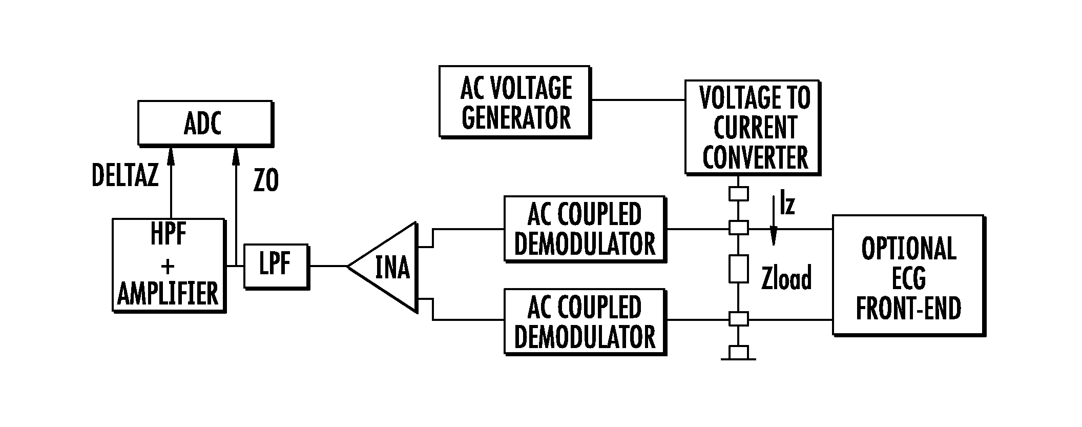
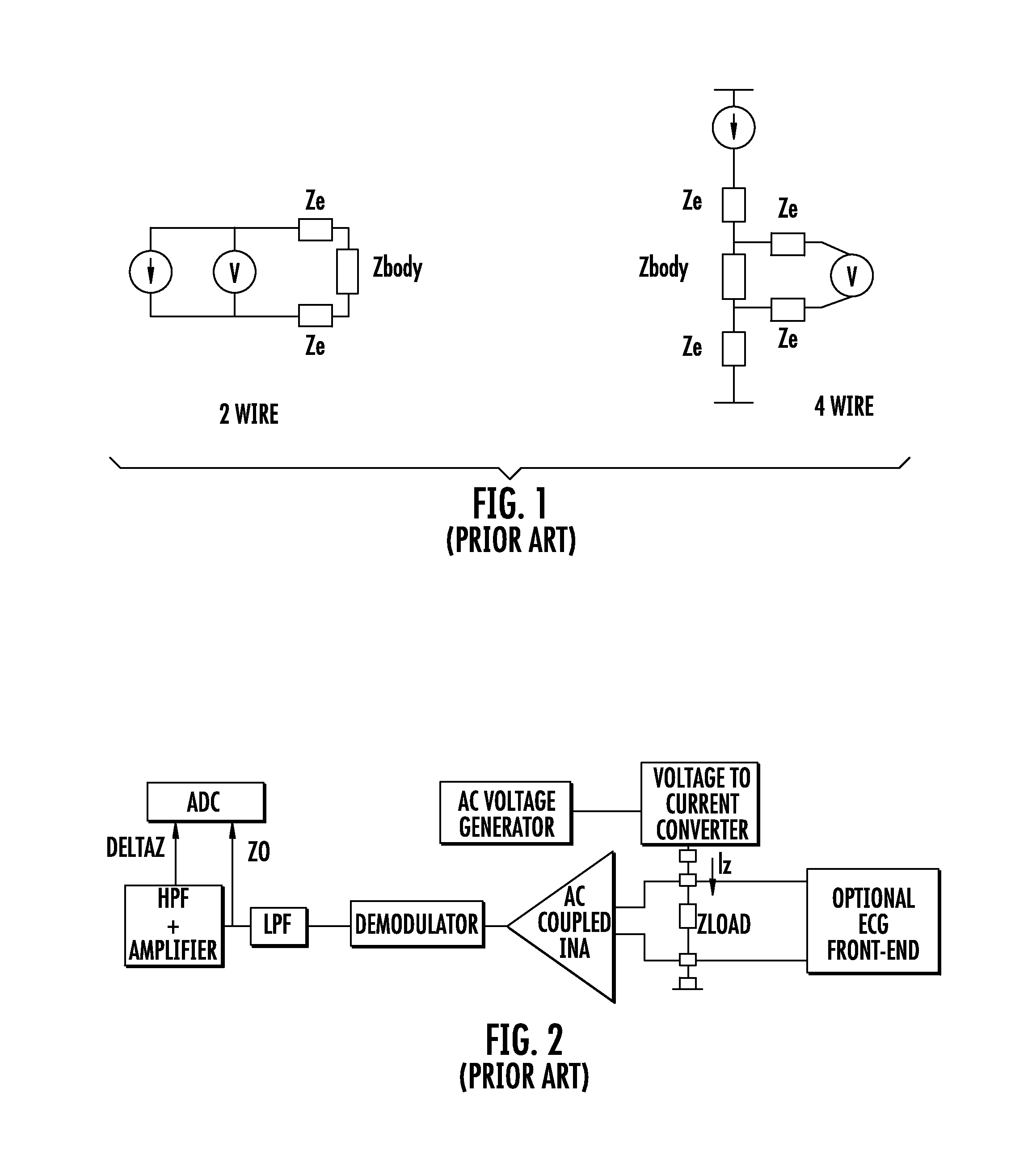
[0044]An embodiment of a device for measuring the impedance of biological tissue is illustrated in FIG. 4. The circuit blocks in common with the prior devices of FIGS. 2 and 3 are identified by the same labels.

[0045]The device has two single-end AM demodulators. Each demodulates the voltage towards ground of a respective electrode and generates a respective baseband signal. The demodulated baseband signals are supplied in input to an INA that generates an amplified copy of their difference.

[0046]Differently from the known device of FIG. 2, the INA amplifies a baseband signal, thus, it has a relatively large gain and a good CMRR in the baseband range of frequencies. Therefore it may be possible to use a low cost and low power consumption INA.

[0047]Differently from the prior device of FIG. 3 disclosed in Rafael Gonzalez-Landaeta, Oscar Casas, and Ramon Pallas-Areny, Heart rate detection from plantar bioimpedance measurements. IEEE Transactions on Biomedical Engineering, 55)3):1163-116...


PUM

PropertyMeasurementUnit
frequencyaaaaaaaaaa
impedanceaaaaaaaaaa
AC voltageaaaaaaaaaa

Abstract

A device for measuring impedance of biological tissue may include electrodes and a voltage-to-current converter coupled to the electrodes to drive an alternating current (AC) through the tissue and sense an AC voltage. The converter may include an amplifier having first and second inputs and an output, a first voltage divider coupled to the first input, a second voltage divider coupled to the second input, a filter capacitor coupled between the output and the second voltage divider, a current limiting resistor coupled between the second input the second voltage divider, and a bypass capacitor coupled to the second input of the amplifier and in parallel with the resistor. A single-ended amplitude modulation (AM) demodulator may demodulate the AC voltage and generate a corresponding baseband voltage representing the impedance. The device may also include an output circuit to generate output signals representative of DC and AC components of the baseband voltage.

Description

FIELD OF THE INVENTION[0001]This invention relates to measurement instruments, and, more particularly, to a device for measuring impedance of biological tissues.BACKGROUND OF THE INVENTION[0002]Measurements of electrical impedance of the human body (bioimpedance) have been studied in bioengineering since the 1960s. These measurements include forcing an alternating current (AC) through the body (usually at a frequency higher than 10 kHz to avoid interference with the electrical activity of nervous and muscular tissues), and sensing the voltage drop between two points.[0003]Water and generally all body fluids (blood, intra and extra cellular fluid, for example) provide the conductive medium of the body. Several measures and studies have been carried on applying this technique in different parts or regions of the body and using different frequencies to target different biological information (See, for example, Deok-Won Kim, Detection of physiological events by impedance, Yonsei Medical...

Claims


Application Information

Patent Timeline
Patent Type & Authority Applications(United States)
IPC IPC(8): A61B5/053G01N33/48G01N33/18G01R27/02G01R1/30
CPCA61B5/053G01R27/02G01N33/48G01N33/18G01R1/30A61B5/0537A61B5/7225A61B2562/0214G01N33/4833G01R27/26Y10T29/49007
Inventor ROSSI, STEFANO
Owner STMICROELECTRONICS SRL
Why Eureka
Try Eureka