Multifrequency synchronous excitation current source used in bio-electrical impedance frequency spectrum measurement

A technology of excitation current source and bioelectrical impedance, which is applied in the directions of diagnostic recording/measurement, application, medical science, etc., can solve the problems such as the difficulty of hardware implementation, low cost, the synchronization excitation signal cannot meet the requirements of data processing, etc., to achieve broadband Wide, high output impedance, high stability effect

Inactive Publication Date: 2011-05-11
XIAN UNIV OF TECH
View PDF5 Cites 15 Cited by
  • Summary
  • Abstract
  • Description
  • Claims
  • Application Information

AI Technical Summary

Problems solved by technology

As far as the current technology is concerned, it is relatively easy to synchronize two signals on the same DDS chip, but it is difficult to achieve synchronization between more signals generated by different DDS chips. or low-cost implementation
The theoretical basis of BIS technology is the Cole-Cole impedance model, and the four parameters of the Cole-Cole impedance model (R 0 , R ∞ , α, τ) requires impedance data of at least 4 frequency points. It can be seen that the synchronous excitation signal containing only two frequency points cannot meet the requirements of subsequent data processing, and only the synchronous excitation signal containing more than 4 frequency points can have Actual measurement application value

Method used


Image

  • Multifrequency synchronous excitation current source used in bio-electrical impedance frequency spectrum measurement
  • Multifrequency synchronous excitation current source used in bio-electrical impedance frequency spectrum measurement
  • Multifrequency synchronous excitation current source used in bio-electrical impedance frequency spectrum measurement

Examples


Embodiment Construction

[0020] The present invention will be described in detail below in conjunction with the accompanying drawings and specific embodiments.

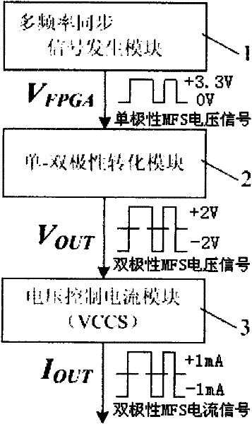
[0021] like figure 1 , the multi-frequency synchronization (Multi-Frequency Synchronizing, referred to as MFS) excitation current source of the present invention includes a multi-frequency synchronization signal generating module 1, a unipolar-bipolar conversion module 2, a voltage-controlled current source module 3 (Voltage-Controlled Current Source, VCCS for short) has three parts.

[0022] The multi-frequency synchronous signal generation module 1 uses FPGA (Field Programmable Gate Array, field programmable gate array) as the carrier, uses Verilog HDL language for hardware programming, and generates unipolar MFS voltage signal V based on the principle of finite state machine (FSM) FPGA .

[0023] The unipolar MFS voltage signal V generated by the FPGA in the multi-frequency synchronous signal generation module 1 is generated by the unipo...


PUM


Abstract

The invention discloses a multifrequency synchronous excitation current source used in bio-electrical impedance frequency spectrum measurement, which comprises a multifrequency synchronous signal generating module, a unipolar-bipolar conversion module, and a voltage control current source module in sequential connection, wherein the multifrequency synchronous signal generating module adopts an FPGA (Field Programmable Gate Array) as a carrier, performs hardware programming through utilizing a Verilog HDL (Hardware Description Language), generates unipolar MFS voltage signal V FPGA based on finite state machine principles, and inputs the signal V FPGA to the unipolar-bipolar conversion module; the unipolar-bipolar conversion module is used for converting unipolar MFS voltage signal V FPGA into symmetric bipolar MFS voltage signal V OUT, and inputting the signal V FPGA into the voltage control current source module; and the voltage control current source module is used for converting the bipolar MFS voltage signal V OUT output by the unipolar-bipolar conversion module into bipolar MFS current signal IOUT and directly exerting the bipolar MFS current signal IOUT onto a tested biomass target receiving BIS (Bispectral) measurement. The multifrequency synchronous excitation current source provided by the invention lays a foundation for the realization of BIS multifrequency synchronous measurement.

Description

technical field [0001] The invention belongs to the technical field of medical electronic instruments and test and measurement, and relates to a multi-frequency synchronous excitation current source for bioelectrical impedance spectrum measurement. Background technique [0002] As a non-invasive detection method, Bioimpedance Spectroscopy (BIS) technology has broad application prospects in the monitoring of human physiological and pathological parameters. BIS measurement usually applies a small alternating current (voltage signal) to the measured object by means of excitation electrodes placed on the body surface, and at the same time detects the voltage (current signal) on the tissue surface through the measurement electrodes, and calculates the corresponding resistance from the measured signal Antibody and its changes, to obtain relevant physiological and pathological information. The technology is cheap, safe, non-toxic and harmless, easy to operate, etc., and has broad ...

Claims


Application Information

Patent Timeline
Patent Type & Authority Applications(China)
IPC IPC(8): A61B5/053
Inventor 杨宇祥康敏航高宗海
Owner XIAN UNIV OF TECH
Why Eureka
Try Eureka