Elastic wave filter device and duplexer

a filter device and duplexer technology, applied in the direction of piezoelectric/electrostrictive/magnetostrictive devices, electrical apparatus, impedence networks, etc., can solve the problems of increasing insertion loss, increasing ohmic loss, and high resistance of idt electrodes, so as to reduce influences, increase ohmic loss, and high output impedance

Inactive Publication Date: 2007-12-27
MURATA MFG CO LTD
View PDF11 Cites 15 Cited by
  • Summary
  • Abstract
  • Description
  • Claims
  • Application Information

AI Technical Summary

Benefits of technology

[0018]In order to overcome the problems described above, preferred embodiments of the present invention provide an elastic wave filter device including a balanced-to-unbalanced conversion function, enables obtaining of balanced output with high output impedance as compared with input-side impedance, and further reduces influences due to a bulk wave without increasing ohmic loss due to an IDT electrode while enabling the reduction of insertion loss in a passband, and also provide a duplexer including such an elastic wave filter device.

Problems solved by technology

Consequently, such as the case of the reception-side filter of cell-phone equipment for DCS or PCS, upon the surface acoustic wave filter being used as a band pass filter whose passband is about 2 GHz, the resistance of IDT electrode becomes high, i.e., ohmic loss increases, and consequently there is no choice other than increasing the insertion loss.
However, the excitation of a bulk wave (SSBW) increases, ripple is readily generated within a passband, thus resulting in a problem wherein insertion loss increases.

Method used


Image

  • Elastic wave filter device and duplexer
  • Elastic wave filter device and duplexer
  • Elastic wave filter device and duplexer

Examples


first preferred embodiment

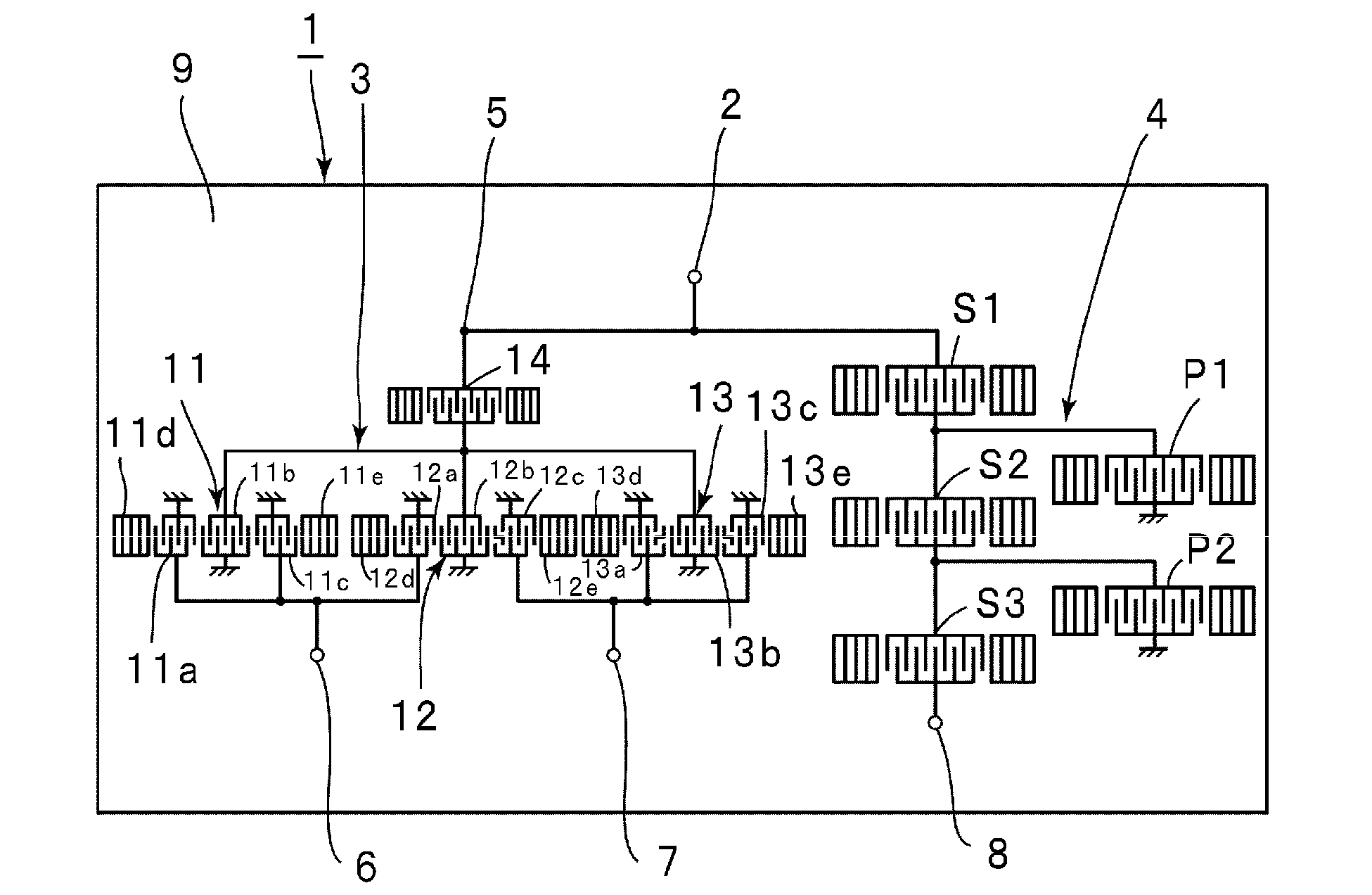
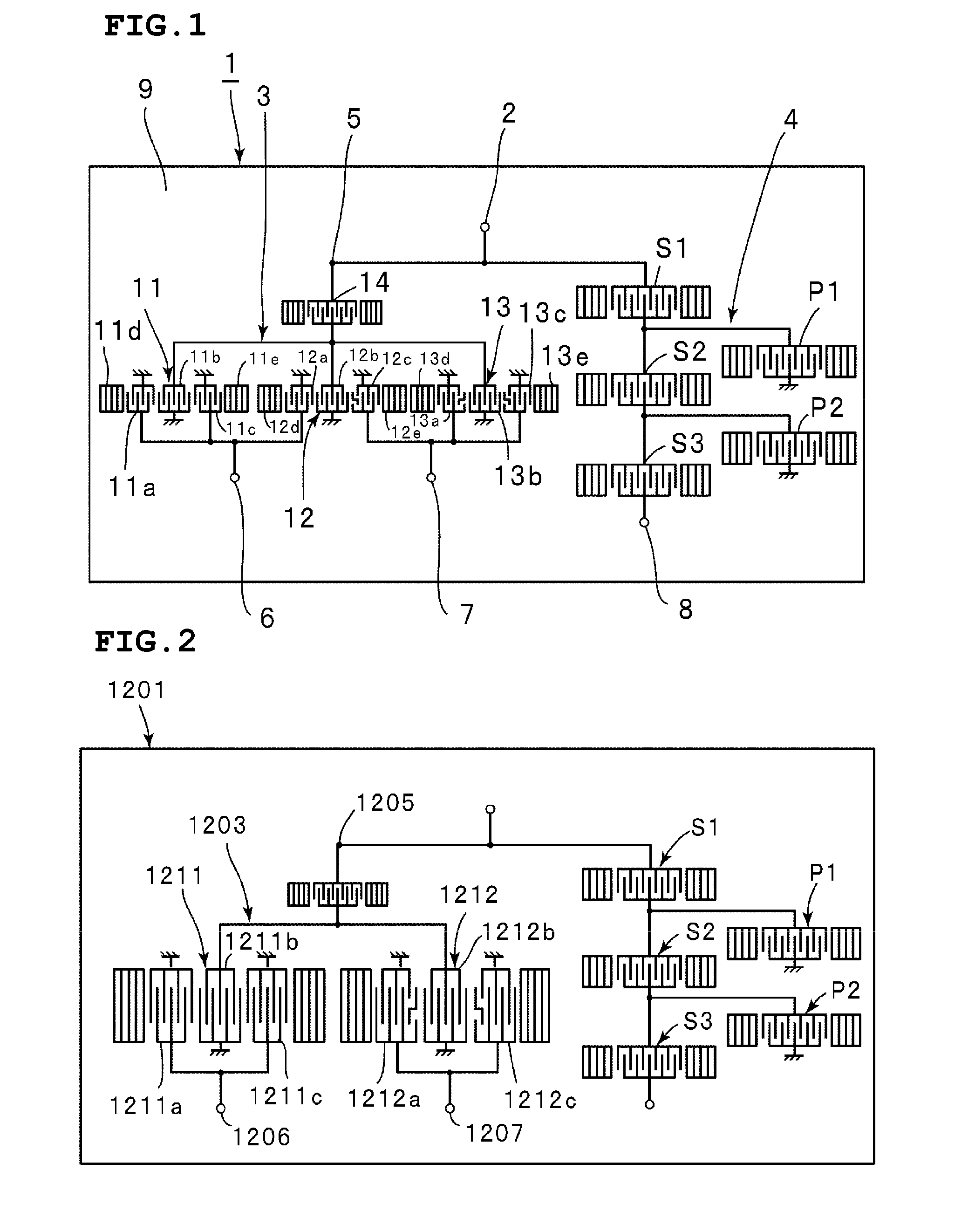
[0039]FIG. 1 is a plan view schematically illustrating the electrode configuration of a duplexer according to a first preferred embodiment of the present invention. A duplexer 1 includes an antenna terminal 2. A reception-side filter preferably including a surface acoustic wave filter device 3 defining one preferred embodiment of the present invention, and a surface acoustic wave filter device 4 having a ladder circuit configuration making up a transmission-side filter, are connected to the antenna terminal 2.

[0040]The surface acoustic wave filter device 3 includes an unbalanced signal terminal 5 connected to the antenna terminal 2, and first and second balanced terminals 6 and 7 defining reception output terminals. On the other hand, with the surface acoustic wave filter device 4, one end is connected to the antenna terminal 2, and the other end is connected to a transmission terminal 8.

[0041]With the duplexer 1 according to a preferred embodiment of the present embodiment, the rec...

second preferred embodiment

[0088]FIG. 6 is a schematic plan view illustrating a surface acoustic wave filter device 31 according to a second preferred embodiment of the present invention. The surface acoustic wave filter device 31 according to the second preferred embodiment generally has the same configuration as the surface acoustic wave filter device 3 according to the first preferred embodiment except that a second longitudinally coupled resonator surface acoustic wave filter 32 differs from the second longitudinally coupled resonator surface acoustic wave filter 12 according to the first preferred embodiment. That is to say, the same reference numerals denote the same components as the case of the first preferred embodiment, thereby citing the description according to the first preferred embodiment, so description thereof will be omitted.

[0089]With the second longitudinally coupled resonator surface acoustic wave filter 32, first to third IDTs 32a to 32c are arranged in the surface wave propagating direc...

third preferred embodiment

[0093]FIG. 7 is a schematic plan view illustrating a surface acoustic wave filter device 41 according to a third preferred embodiment of the present invention.

[0094]With the surface acoustic wave filter device 41, first ends of second IDTs 51b to 53b of the centers of first to third longitudinally coupled resonator surface acoustic wave filters 51 to 53 defining 3-IDT type filters are connected to the unbalanced signal terminal 5. Second ends of the second IDTs 51b to 53b are connected to ground.

[0095]On the other hand, first and third IDTs 51a and 51c of the first longitudinally coupled resonator surface acoustic wave filter 51 are connected to a first end of first and third IDTs 54a and 54c of a fourth longitudinally coupled resonator surface acoustic wave filter 54 by first and second signal lines 61 and 62. The second end of the first and third IDTs 51a and 51c, and the second ends of the IDTs 54a and 54c are connected to ground.

[0096]Similarly, first ends of first and third IDT...


PUM


Abstract

In an elastic wave acoustic device, input ends of first to third longitudinally coupled resonator surface acoustic wave filters are connected to an unbalanced signal terminal, the output end of the first longitudinally coupled resonator surface acoustic wave filter, and a first IDT defining a first output terminal of the second longitudinally coupled resonator surface acoustic wave filter are connected to a first balanced signal terminal, the output end of the third longitudinally coupled resonator surface acoustic wave filter, and a third IDT defining a second output terminal of the second longitudinally coupled resonator surface acoustic wave filter are connected to a second balanced signal terminal, and the phase of an output signal to an input signal of the first longitudinally coupled resonator surface acoustic wave filter differs by about 180 degrees from the phase of an output signal to an input signal of the third longitudinally coupled resonator surface acoustic wave filter. Thus, the elastic wave filter device has a balanced-to-unbalanced conversion function and an impedance conversion function, and reduces an insertion loss within a passband.

Description

BACKGROUND OF THE INVENTION[0001]1. Field of the Invention[0002]The present invention relates to an elastic wave filter device utilizing a surface acoustic wave and an elastic boundary wave, and more particularly, the present invention relates to an elastic wave filter device configured by connecting a plurality of longitudinally coupled resonator elastic wave filters, and a duplexer including such an elastic wave filter device thereof.[0003]2. Description of the Related Art[0004]With cell phones, there has been demand for a reduction in the number of components, to realize reduction in size. Consequently, there has been demand for one component to have multiple functions. Balanced duplexers have been developed as one example of a component including such multiple functions. Balanced duplexers include a transmission-side filter connected to an antenna terminal, and a reception-side filter having a balanced-to-unbalanced conversion function. The reception-side filter has a balanced-t...

Claims


Application Information

Patent Timeline
Patent Type & Authority Applications(United States)
IPC IPC(8): H03H9/72H03H9/64
CPCH03H9/0028H03H9/0071H03H9/725H03H9/0085H03H9/008
Inventor TAKAMINE, YUICHI
Owner MURATA MFG CO LTD
Why Eureka
Try Eureka