Filler for separator equipment
A separator and equipment technology, applied in the direction of filtration separation, separation method, gravity filter, etc., can solve the problems of poor filtration effect, troublesome use, inconvenient cleaning and replacement, etc., and achieve the effect of fixation and stability
- Summary
- Abstract
- Description
- Claims
- Application Information
AI Technical Summary
Problems solved by technology
Method used
Image

Examples
Embodiment 1
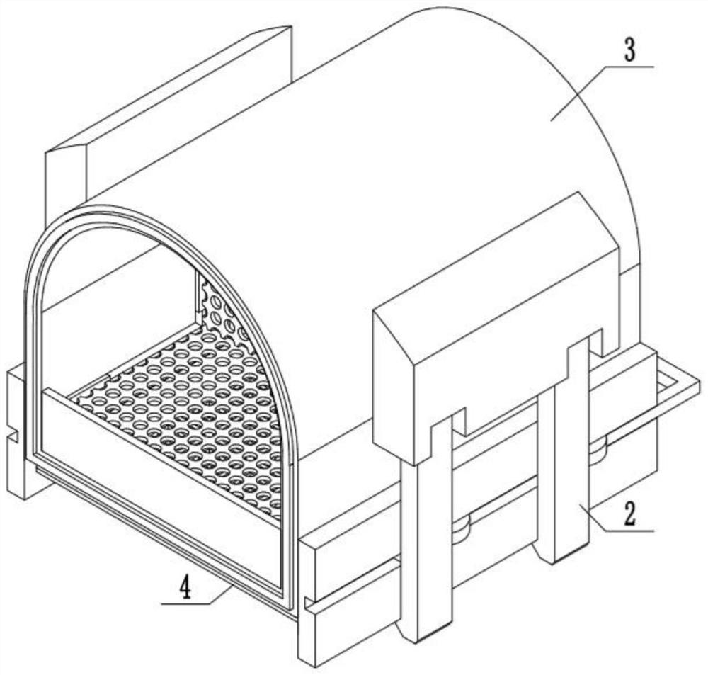
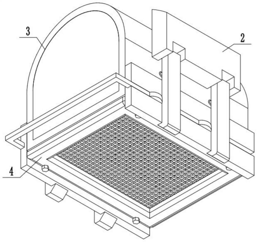
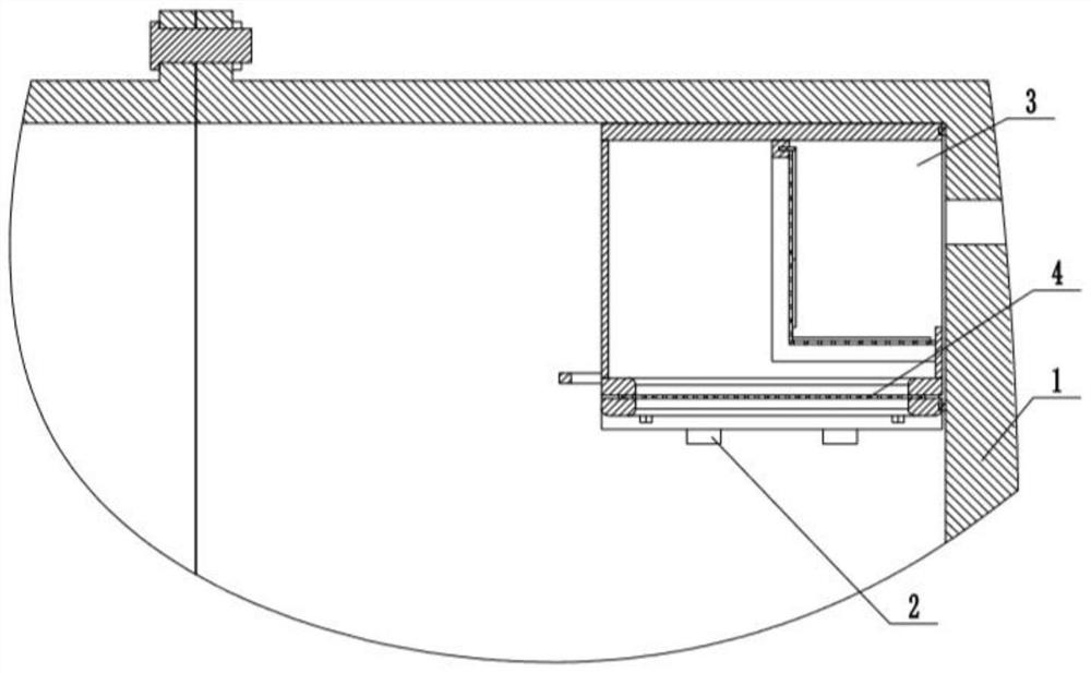
[0039] Embodiment one, combining Figure 1-Figure 10 Be explained:
[0040] A filler for separator equipment, comprising: a separator 1 and a bottom filter mechanism 4, the bottom filter mechanism 4 is located inside the separator 1, fixed clamping mechanisms 2 are symmetrically installed on both sides of the filler mechanism 3, and the bottom filter mechanism 4 Installed below the filling mechanism 3, the fixed clamping mechanism 2 is fixedly installed in the separator 1, the filling mechanism 3 is located at the liquid inlet of the separator 1, the fixed clamping mechanism 2 can realize the fixing of the filling mechanism 3, and the filling mechanism 3 The mixed liquid can be filtered to remove impurities, and the bottom filter mechanism 4 can further filter the mixed liquid.
Embodiment 2
[0041] Embodiment two, combining Figure 1-Figure 10 Be explained:
[0042]The fixed clamping mechanism 2 includes: a fixed block 2-1, a mounting lever 2-2, a tension spring 2-3, a mounting plate 2-4, a control handle 2-5 and a control rod 2-6, and the fixed block 2- The upper part of 1 is fixedly installed on the separator 1, the lower part of the fixed block 2-1 is installed with the installation lever 2-2 through the shaft movement, and the trapezoidal slider 2-7 is installed through the trapezoidal chute set on the installation lever 2-2 On the installation lever 2-2, the two ends of the tension spring 2-3 are respectively fixedly installed on the trapezoidal slider 2-7 and the packing mechanism 3 by welding, and the mounting plate 2-4 is fixedly installed on the packing mechanism 3 by welding, The installation bar 2-2 is in contact with the installation plate 2-4, the installation plate 2-4 is provided with a chute, the control rod 2-6 is slidably installed in the chute,...
Embodiment 3
[0044] Embodiment three, combining Figure 1-Figure 10 Be explained:
[0045] Described packing mechanism 3 comprises: outer frame body 3-1, overflow baffle plate 3-2 and tailgate 3-3, overflow baffle plate 3-2 is installed on the front end face of outer frame body 3-1, outer frame The rear end face of body 3-1 is equipped with tailgate 3-3, and the both sides of outer frame body 3-1 is fixedly installed with mounting plate 2-4, and one end of tension spring 2-3 is connected with the side surface of outer frame body 3-1. contact;
[0046] The front end of the outer frame body 3-1 is provided with a mounting groove, and a sealing rubber strip 3-4 is installed in the mounting groove. The lower surface of the outer frame body 3-1 is a square frame body 3-5, and the square Threaded holes are provided at the bottom of the frame body 3-5;
[0047] The outer frame body 3-1 is provided with a primary filter mechanism 3-6;
[0048] The primary filter mechanism 3-6 includes: a slot ...
PUM
 Abstract
Description
Claims
Application Information
 - R&D
- Intellectual Property
- Life Sciences
- Materials
- Tech Scout
- Unparalleled Data Quality
- Higher Quality Content
- 60% Fewer Hallucinations
Browse by: Latest US Patents, China's latest patents, Technical Efficacy Thesaurus, Application Domain, Technology Topic, Popular Technical Reports.
© 2025 PatSnap. All rights reserved.Legal|Privacy policy|Modern Slavery Act Transparency Statement|Sitemap|About US| Contact US: help@patsnap.com