Gantry type lathe workpiece clamping system

A workpiece clamping and gantry-type technology, which is applied in metal processing and other directions, can solve the problems of workpiece falling off, uneven force, and heavy workpiece, so as to achieve good clamping work and improve processing efficiency.

Inactive Publication Date: 2022-01-04
张传保
View PDF1 Cites 1 Cited by
  • Summary
  • Abstract
  • Description
  • Claims
  • Application Information

AI Technical Summary

Problems solved by technology

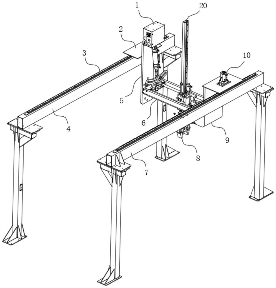
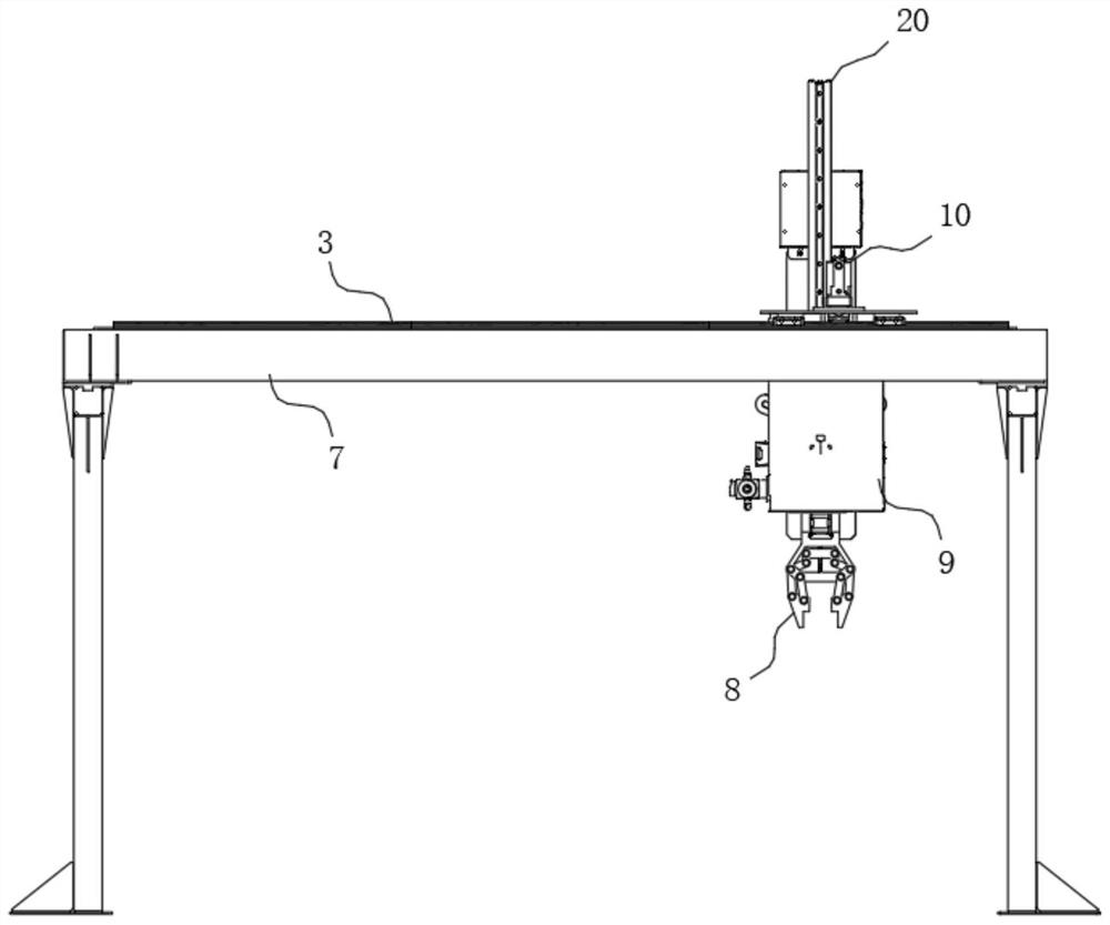
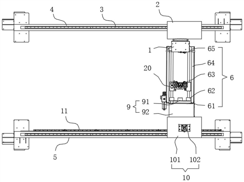
[0003] For example, the patent number CN202010126762.1 discloses a gantry-type lathe workpiece clamping system, including a column, a beam, a longitudinal beam, a chip removal device, a telescopic electric cylinder, a rotary electric cylinder, claws I, and claws II; the two ends of the beam are fixed At the top of the column, both ends of the longitudinal beam are movably connected to the crossbeam, the chip removal device is located at one end of the longitudinal beam and is movably connected to the crossbeam and the longitudinal beam, the telescopic electric cylinder is movably connected to the longitudinal beam, the rotary electric cylinder is fixedly connected to the telescopic electric cylinder, and the claws I and claws II are respectively fixedly connected to the rotary electric cylinder; in the present invention, there are chip removal devices, claws I and claws II, which can complete the clamping of square and round blanks, and at the same time, the chip removal device can complete the clamping during the clamping process. However, when the manipulator clamps a heavy workpiece to adjust the tilt angle, because the workpiece is relatively heavy, it is easy to cause uneven force on the two main jaws in the manipulator, thus It is easy to cause the workpiece to fall off

Method used


Image

  • Gantry type lathe workpiece clamping system
  • Gantry type lathe workpiece clamping system
  • Gantry type lathe workpiece clamping system

Examples


Embodiment Construction

[0033] The following will clearly and completely describe the technical solutions in the embodiments of the present invention with reference to the accompanying drawings in the embodiments of the present invention. Obviously, the described embodiments are only some of the embodiments of the present invention, not all of them. The components of the embodiments of the invention generally described and illustrated in the figures herein may be arranged and designed in a variety of different configurations. Accordingly, the following detailed description of the embodiments of the invention provided in the accompanying drawings is not intended to limit the scope of the claimed invention, but merely represents selected embodiments of the invention. Based on the embodiments of the present invention, all other embodiments obtained by those skilled in the art without making creative efforts belong to the protection scope of the present invention.

[0034] In describing the embodiments o...


PUM


Abstract

The invention discloses a gantry type lathe workpiece clamping system. A first telescopic rod stretches out and draws back so that a connecting shaft can move to work in an arc groove in the upper side of an arc groove supporting block; and a second through hole connecting column is rotationally connected with a second fixing shaft in a sleeving mode, and a first through hole connecting column is rotationally connected with a fixing rotating shaft in a sleeving mode so that when the connecting shaft moves to work in the arc groove in the upper side of the arc groove supporting block, a whole swing type supporting frame mechanism can be driven to conduct angle adjusting work, and accordingly, a height adjusting mechanism and a mechanical arm assembly can be driven to conduct angle adjusting work. Due to the fact that a controller is electrically connected with a mechanical switch and a servo motor, when the mechanical switch makes contact with a semicircular protruding block, the servo motor works again, the mechanical arm assembly conducts clamping work again, the phenomenon that a workpiece falls off is avoided during angle adjusting work, and accordingly, the machining efficiency is improved.

Description

technical field [0001] The invention relates to the technical field of lathe machining and clamping, in particular to a gantry type lathe workpiece clamping system. Background technique [0002] Lathe processing is an indispensable processing method in mechanical processing. As the automation process becomes faster and faster, the loading and unloading of lathe processing is gradually automated. When processing, a manipulator will be used. The manipulator is a kind of An automatic operating device that can imitate certain actions and functions of the human hand and arm to grab, carry objects or operate tools according to a fixed program; its feature is that it can be programmed to complete various expected operations, and its structure and performance are both human and mechanical The advantages of each mobile phone. [0003] For example, the patent number CN202010126762.1 discloses a gantry-type lathe workpiece clamping system, including a column, a beam, a longitudinal be...

Claims


Application Information

Patent Timeline
Patent Type & Authority Applications(China)
IPC IPC(8): B23B15/00B23Q7/04
CPCB23Q7/04B23Q7/043
Inventor 张传保
Owner 张传保
Why Eureka
Try Eureka