Automatic clamp spring mounting device
An automatic installation and circlip technology, applied in metal processing equipment, metal processing, manufacturing tools, etc., can solve the problem of limited application scope of circlip automatic installation, improve the automation efficiency of circlip assembly, reduce the separation of the axial sleeve The possibility of the barrel, the effect of reducing the force requirements of the plug-in connection
- Summary
- Abstract
- Description
- Claims
- Application Information
AI Technical Summary
Problems solved by technology
Method used
Image

Examples
Embodiment 1
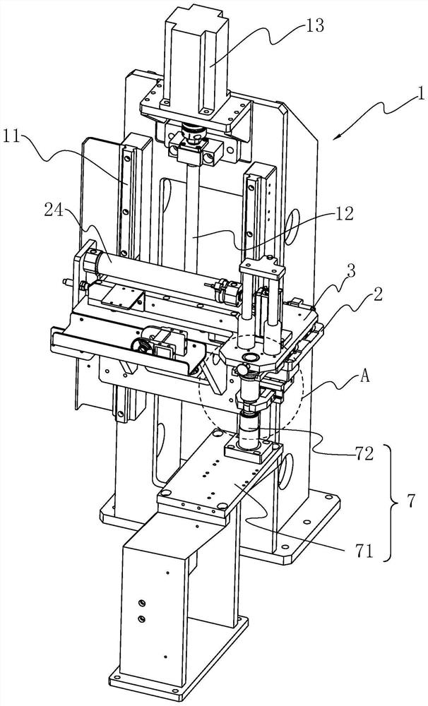
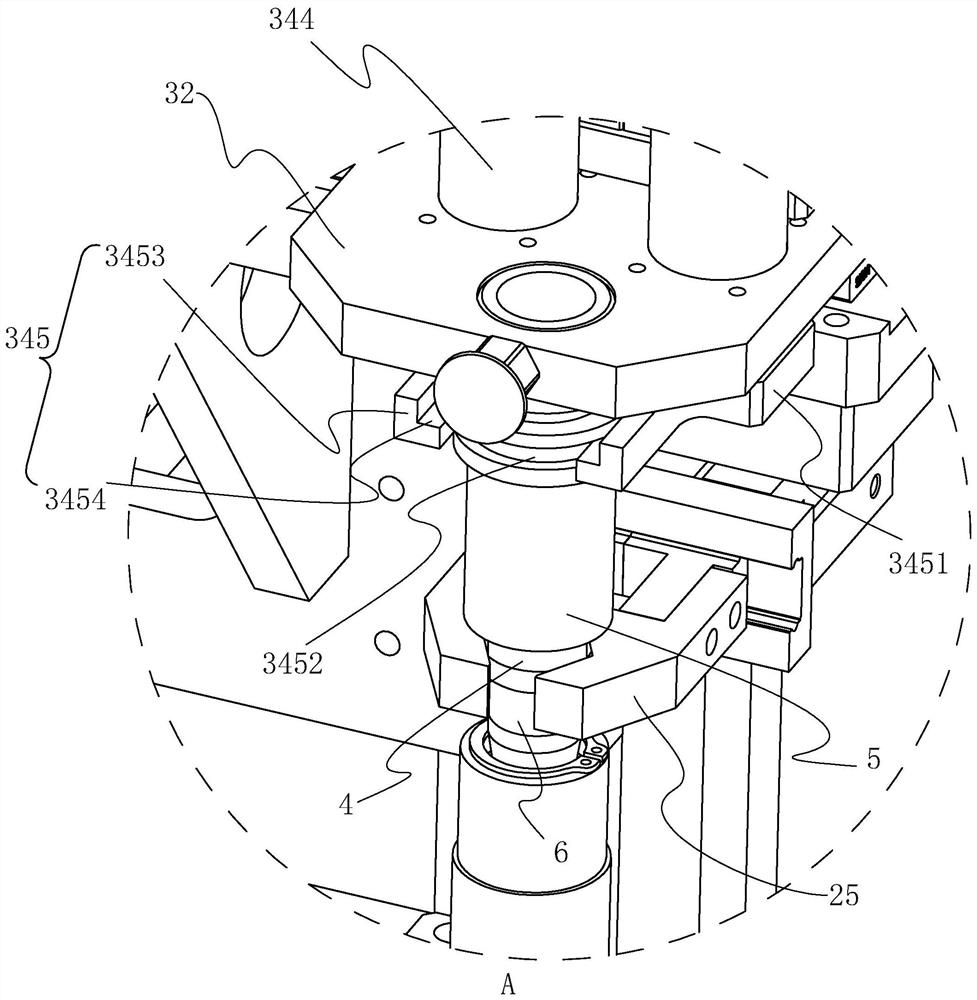
[0061] refer to figure 2 , a kind of circlip automatic installation device comprises frame 1, and frame 1 comprises the longitudinal installation frame perpendicular to the ground, and the axial slide rail 11 that extends along its height direction is installed on the longitudinal installation frame, and axial slide rail 11 is two and distributed symmetrically, the axial slide rails 11 are installed and fixed with the longitudinal mounting frame by bolt fasteners 33 . The position between the two axial slide rails 11 on the longitudinal mounting frame is provided with two mounting seats, and the two mounting seats are respectively arranged at the two ends of the axial slide rails 11, and a rotatable joint is connected between the two mounting seats. The lead screw 12, two mounts provide positioning for the lead screw 12, the drive motor 13 is installed on the longitudinal mounting frame, the rotating shaft of the drive motor 13 is fixedly installed with the lead screw 12, and...
Embodiment 2
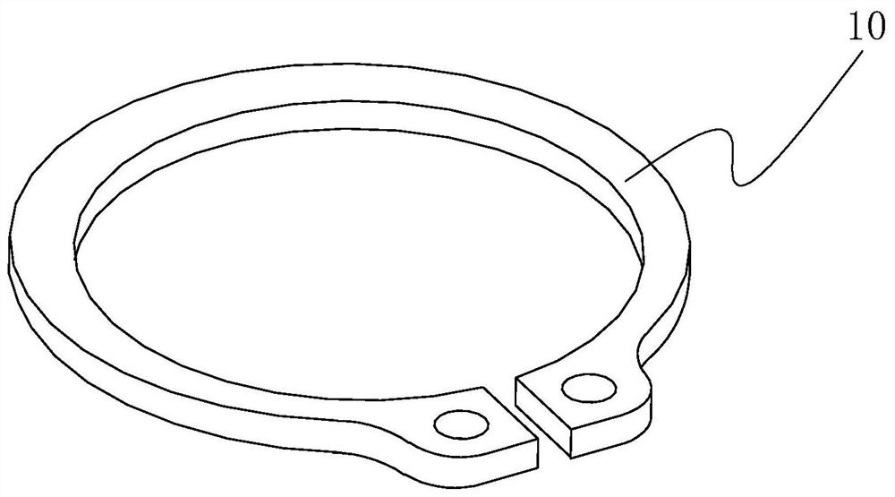
[0078] refer to Figure 9 with Figure 10 , The difference between this embodiment and Embodiment 1 is that a feeding device 73 is also installed on the feeding table 7, and the feeding device 73 includes a feeding table 731, and the feeding table 731 is located on the workbench 71 and is located On one side of the sleeve 72, a stop bar 732 is symmetrically arranged on the feeding table 731, and the stop bar 732 is perpendicular to the feeding table 731, and a trough for accommodating the jump spring 10 is formed between the stop bar 732, and the stop bar 732 is opposite. A limit plate 733 is also provided between 732, and one end of the limit plate 733 is placed in the trough, and when the clip spring 10 is filled in the trough, the end of the limit plate 733 located in the trough is placed in the notch of the clip spring 10 ; The feeding table 731 is located at the bottom of the trough and has a discharge port, and the feeding table 731 is located below the discharge port a...
Embodiment 3
[0081] refer to Figure 11The difference between this embodiment and Embodiment 1 is that the separation device 8 is a separation cylinder 84, and the separation cylinder 84 is installed on the side of the lifting platform 2 away from the horizontal platform 3 by a bolt fastener 33, and the expansion and contraction of the separation cylinder 84 A separation mounting plate is installed on the rod, the first clamping device 25 is mounted on the separation mounting plate, and the separation cylinder 84 drives the first clamping device 25 to move up and down along the axial direction of the sleeve 4 .
[0082] The implementation principle of Embodiment 3 is: when the material placement sleeve 72 pushes and transfers the circlip 10 to the axial sleeve 4, the transition cylinder 6 is not left in the axial hole 721 of the material placement sleeve 72, but The displacement sleeve 72 is axially removed together with the axial sleeve 4, and then the first clamping device 25 clamps the ...
PUM
 Abstract
Description
Claims
Application Information
 - R&D
- Intellectual Property
- Life Sciences
- Materials
- Tech Scout
- Unparalleled Data Quality
- Higher Quality Content
- 60% Fewer Hallucinations
Browse by: Latest US Patents, China's latest patents, Technical Efficacy Thesaurus, Application Domain, Technology Topic, Popular Technical Reports.
© 2025 PatSnap. All rights reserved.Legal|Privacy policy|Modern Slavery Act Transparency Statement|Sitemap|About US| Contact US: help@patsnap.com