Mobile trolley with buffer mechanism for European style crane

A technology of buffer mechanism and mobile trolley, which is applied in the direction of traveling mechanism, load block, mechanical equipment, etc., can solve the problems of reducing the scope of application, not having an installation adjustment structure, not having a buffer protection structure, etc., and achieves the effect of improving the scope of application

Pending Publication Date: 2022-01-04
合肥市春华起重机械有限公司
View PDF1 Cites 1 Cited by
  • Summary
  • Abstract
  • Description
  • Claims
  • Application Information

AI Technical Summary

Problems solved by technology

[0004] The existing mobile trolley for European cranes with a buffer mechanism has certain disadvantages in the process of use. The traditional mobile trolley for European cranes does not have an installation and adjustment structure, so that the mobile trolley for European cranes can only be used for European cranes of the corresponding model. Its scope of application is reduced; secondly, the traditional European-style mobile trolley for cranes does not have an auxiliary limit structure, which makes the mobile trolley for European-style cranes prone to derailment during use, and the safety is poor; at the same time, the traditional European-style mobile trolley for cranes does not have buffer protection structure, which reduces the stability of its use and brings certain adverse effects to users

Method used


Image

  • Mobile trolley with buffer mechanism for European style crane
  • Mobile trolley with buffer mechanism for European style crane
  • Mobile trolley with buffer mechanism for European style crane

Examples


Embodiment 1

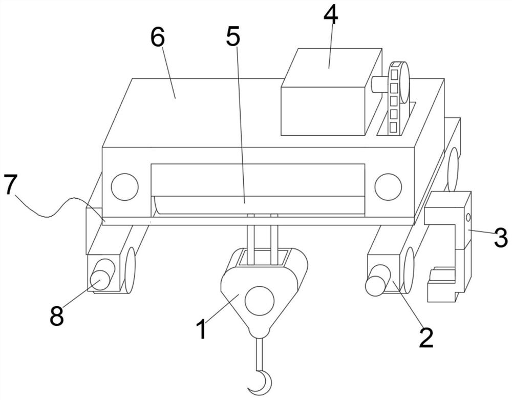
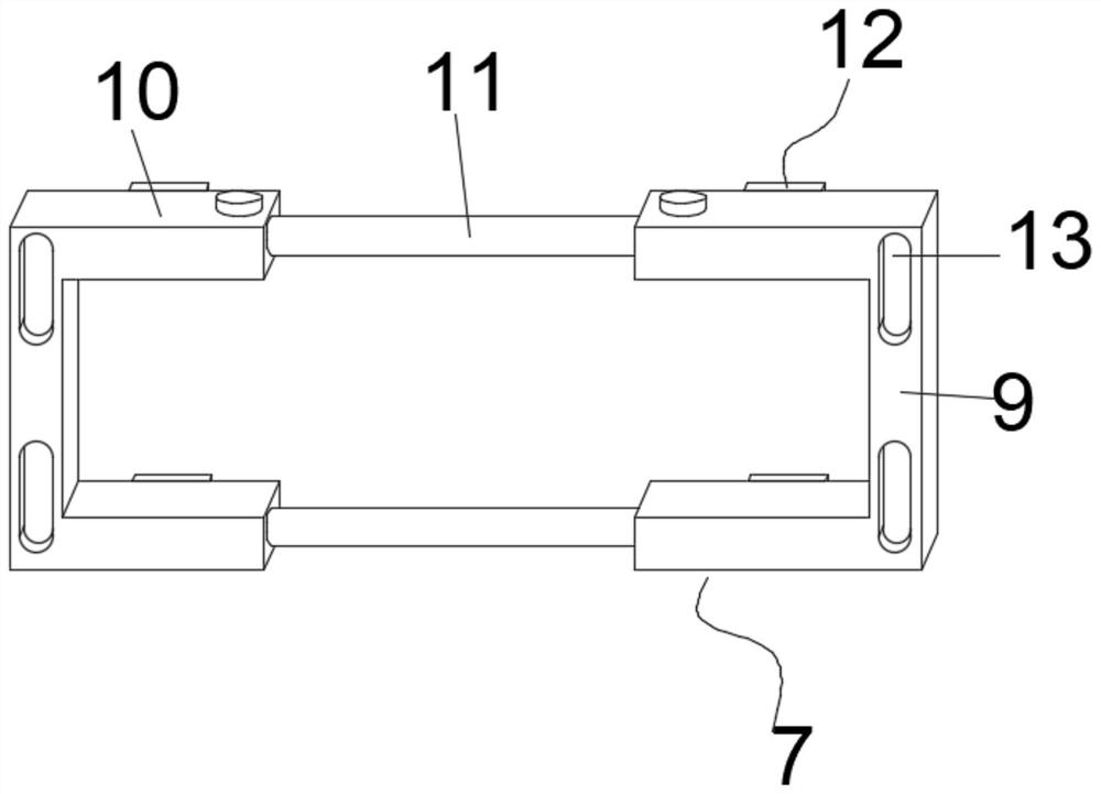
[0035] The combined frame 7 includes a first card frame 9 and a second card frame 10, which are flexibly connected by two sets of telescopic columns 11. When the combined frame 7 is in use, the user can The size of the base 2 and the sealing cover 6 pulls the first card frame 9 and the second card frame 10 of the combination frame 7, so that the telescopic column 11 is drawn out from between the first card frame 9 and the second card frame 10, thereby adjusting the combination The use size of frame 7.

[0036] The inner sides of the first card frame 9 and the second card frame 10 are all provided with cylindrical grooves for installing the telescopic column 11, and the sides of the first card frame 9 and the second card frame 10 are equipped with locking and fixed telescopic slots. The bolts of the column 11, when the telescopic column 11 is used, utilize the setting of the columnar groove pair to make the telescopic column 11 play the role of telescopic adjustment, and after ...

Embodiment 2

[0039] The outer surfaces of the first card frame 9 and the second card frame 10 are provided with two sets of waist-shaped notches 13 for fixing the mobile base 2 with gaskets. By using the settings of the waist-shaped notches 13, the gaskets can be matched by bolts. It plays a fixed role in the installation of the first card frame 9 and the second card frame 10, and its installation position can be adjusted appropriately through the structure of the waist-shaped notch 13 itself.

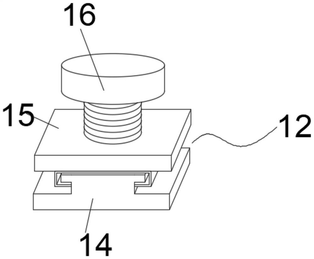
[0040] The sliding fixture 12 includes a lower clamping plate 14 and an upper clamping plate 15, the upper clamping plate 15 is movably installed on the top of the lower clamping plate 14, the lower clamping plate 14 and the upper clamping plate 15 are butted through a draw-in groove, and the middle part of the lower clamping plate 14 and the upper clamping plate 15 is sleeved with a tight The fastening bolt 16, when the sliding clamp 12 is used, by inserting the fastening bolt 16, the lower clampin...

Embodiment 3

[0042] One end of the buffer column 8 is movably socketed with a fixed block 23, and a spring 17 is installed inside the fixed block 23, and the middle part of one end of the fixed block 23 is movably socketed with a threaded sleeve rod 18. When the buffer column 8 is in use, the user The spring 17 can be squeezed by rotating one end of the threaded sleeve rod 18, thereby adjusting the softness and hardness of the spring 17. When the buffer post 8 hits, the spring 17 can play an elastic buffering effect on the buffer post 8.

[0043] One side of the auxiliary tripod 3 is provided with a telescopic block 21, and the auxiliary tripod 3 and the mobile base 2 are flexibly connected by the telescopic block 21. When the auxiliary tripod 3 is in use, the installation of the auxiliary tripod 3 can be adjusted by using the telescopic block 21. Position, so that the auxiliary tripod 3 can be adjusted according to the position of the beam of the European crane. At the same time, after the...


PUM


Abstract

The invention discloses a mobile trolley with a buffer mechanism for an European style crane. The mobile trolley comprises a moving base and a sealing cover, the sealing cover is fixedly installed on the upper portion of the moving base, trundles driven by a motor are arranged at the bottom of the moving base, a combined frame used for fixing and adjusting is arranged between the moving base and the sealing cover, auxiliary scaffolds used for assisting in fixing are arranged in the middle of the side edges of the moving base, and buffer columns are movably installed at the front end of the moving base. According to the mobile trolley with the buffer mechanism for the European style crane, by arranging a sliding clamp, the combined frame is provided with multiple adjusting structures, and the combined frame can be correspondingly mounted and adjusted according to the structures of the European style crane and the moving trolley, so that the moving trolley for the European style crane is provided with a mounting adjusting structure, and the application range of the moving trolley is widened; and through arrangement of the auxliary scaffolds, the moving trolley for the European style crane is provided with an adjustable auxiliary fixing structure, and the safety of the moving trolley for the European style crane during adaptive use is improved.

Description

technical field [0001] The invention belongs to the technical field of cranes, in particular to a mobile trolley for European-style cranes with a buffer mechanism. Background technique [0002] The European-style crane has the advantages of light weight, compact structure and low energy consumption. A trolley and a lifting mechanism are installed on the bridge frame. The trolley can run forward and backward, and the cart can run and other mechanisms to realize the transportation of materials and objects in three-dimensional space. The European-style crane adopts The unique design concept has the characteristics of small size, light weight and small wheel pressure. [0003] The patent document of patent No. CN204727458U discloses a European-style crane trolley, which includes a trolley frame, a support frame and a rear wheel shaft are arranged on the trolley frame, and a driving device is provided on the support frame. Both ends of the output shaft of the driving device are ...

Claims


Application Information

Patent Timeline
Patent Type & Authority Applications(China)
IPC IPC(8): B66C11/16B66C9/10B66C15/04F16F15/067
CPCB66C11/16B66C9/10B66C15/04F16F15/067
Inventor 梁大伟
Owner 合肥市春华起重机械有限公司
Why Eureka
Try Eureka