
Pavement joint cutting device for highway bridge construction and joint cutting method thereof

A technology for highway bridges and slitting, which is applied in bridges, bridge construction, erection/assembly of bridges, etc., can solve the problems of straight slitting of concrete pavements of highway bridges, bulky slitting devices, and affecting the quality of slitting construction.

Inactive Publication Date: 2022-01-04
邢丞
View PDF0 Cites 0 Cited by
  • Summary
  • Abstract
  • Description
  • Claims
  • Application Information

AI Technical Summary

Problems solved by technology

[0004] And existing technology all is to carry out seam cutting by artificial relying on feeling when cutting seam, has the problem that it is difficult to cut straight seam on highway bridge concrete pavement, has a strong impact on the construction quality of seam cutting on road bridge concrete pavement, and artificial concrete When cutting the pavement, it is time-consuming and laborious, and there is also the problem of difficulty in controlling the construction depth of the concrete pavement cutting of highway bridges, which makes the construction difficult. At the same time, most of the operating cutting devices are bulky, difficult to control, difficult to transport, and take up space for storage At the same time, the existing method of using the concrete pavement slit device for highway bridge construction has complicated and unreasonable operation steps, which leads to low construction efficiency and seriously affects the construction quality of the slit on the concrete pavement of the highway bridge
[0005] Therefore, in view of the ubiquitous shortcomings of the slitting device and slitting method in the prior art that the slit is not straight, the device is bulky, difficult to carry, takes up space, and has complicated operating steps, there is an urgent need for a slitting device with a simple structure and easy operation. Sewing device and cutting method

Method used


Image

  • Pavement joint cutting device for highway bridge construction and joint cutting method thereof
  • Pavement joint cutting device for highway bridge construction and joint cutting method thereof
  • Pavement joint cutting device for highway bridge construction and joint cutting method thereof

Examples


Embodiment 1

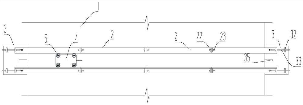
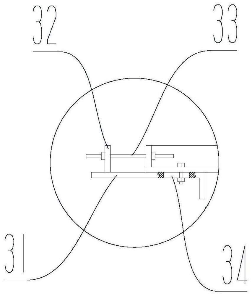
[0039] Please refer to Figure 1 ~ Figure 3 , figure 1 It is a top view of the slitting device according to the embodiment of the present invention; figure 2 It is the front view of the cutting device according to the embodiment of the present invention; image 3 for figure 2 Enlarged image at A.

[0040] A road surface cutting device for highway bridge construction, comprising two retaining rods 2 oppositely arranged on the road surface 1, the bottom surface of the retaining rods 2 is attached to the road surface 1, and a spacer is formed between the two oppositely disposed retaining rods 2. The guide groove that the seam cutter 4 walks, the guide groove carries out spacing and guidance to the walking direction of the seam cutter 4, ensures the precision of the seam cutter 4 walking, and guides it to cut out the vertical slit.

[0041] In the present invention, the model of the slitting machine 4 is not limited. In this embodiment, a chiniu road cutting machine is adop...

Embodiment 2

[0045] Please refer to Figure 1 ~ Figure 3 , figure 1 It is a top view of the slitting device according to the embodiment of the present invention; figure 2 It is the front view of the cutting device according to the embodiment of the present invention; image 3 for figure 2 Enlarged image at A.

[0046] This embodiment proposes a road surface cutting device for highway bridge construction, which has basically the same structure as that of Embodiment 1, and the similarities will not be repeated. Angle steel 21, detachable connection between any two adjacent angle steels 21.

[0047] In this embodiment, each retaining rod 2 is formed by successively connecting multiple angle steels 21, and the two adjacent angle steels 21 are detachably connected. It is connected as a whole, and when not in use, the retaining rod 2 is disassembled with multiple angle steels 21, so as to reduce the difficulty of carrying and placing the tools.

[0048] The angle steel 21 is an L-shaped ...

Embodiment 3

[0050] Please refer to Figure 1 ~ Figure 3 , figure 1 It is a top view of the slitting device according to the embodiment of the present invention; figure 2 It is the front view of the cutting device according to the embodiment of the present invention; image 3 for figure 2 Enlarged image at A.

[0051] This embodiment proposes a road surface cutting device for highway bridge construction, which is basically the same in structure as Embodiment 2, and the similarities will not be repeated. The difference is that the two ends of each angle steel 21 in this embodiment are A connecting plate 22 is provided, and the connecting plate 22 between two adjacent angle steels 21 is connected by bolts.

[0052] In this embodiment, the connecting plate 22 is welded to both ends of the angle iron 21, and the connecting plate 22 is vertically arranged relative to the angle iron. Because the baffle bar 2 adopts a segmental structure, the connecting plate 22 is used for connecting and ...


PUM


Abstract

The invention provides a pavement joint cutting device for highway bridge construction and a joint cutting method thereof, and relates to the field of road construction equipment. The joint cutting device comprises two stop levers oppositely arranged on the pavement, end plates are arranged at the two ends of each stop lever, the stop levers are fixed to the pavement through the end plates, and a joint cutting machine is arranged between the two stop levers. The joint cutting method comprises the steps that two opposite stop levers are arranged on the pavement; end plates for fixing the stop levers are arranged at the two ends of the two stop levers; the joint cutting machine is placed between the two oppositely-arranged stop levers, and the joint cutting machine walks in a guide groove to cut the pavement. According to the joint cutting device, the two opposite stop levers are arranged, and the guide groove allowing the joint cutting machine to linearly walk is formed between the stop levers and the pavement; the end plates are arranged at the two ends of the stop levers respectively, so that the stop levers cannot move even if the joint cutting machine impacts or extrudes the stop levers in the walking process, and linear walking of the joint cutting machine is guaranteed.

Description

technical field [0001] The invention relates to the field of road construction equipment, in particular to a road surface cutting device for road bridge construction and a cutting method thereof. Background technique [0002] Highway and bridge engineering refers to the planning, design, construction, maintenance, and repair of structures across waters, valleys, and all traffic channels. In large deep valleys, or across other traffic lines, bridges need to be erected in order to keep traffic flowing. Sometimes elevated roads composed of viaducts are required in bustling urban areas. The route next to the mountain may be due to the huge excavation of the roadbed or the instability of the geological structure. Or to protect the landscape, sometimes viaducts are built instead of subgrades. Bridges crossing rivers are generally equipped with high-water level bridges that can safely release the expected maximum flood. [0003] Expansion joints of highway bridges are specially re...

Claims


Application Information

Patent Timeline
Patent Type & Authority Applications(China)
IPC IPC(8): E01C23/09E01D21/00
CPCE01C23/0933E01D21/00
Inventor 邢丞王绍然王云峰张松波焦永培
Owner 邢丞
Learn More