
Unmanned inspection trolley for bottom of oversize steel beam bridge

A technology of trolleys and section steel, applied in bridges, bridge parts, bridge construction, etc., can solve the problems of low manual detection efficiency, poor working conditions, and poor results, so as to improve detection efficiency and detection effect, reduce costs, and reduce safety risks Effect

Active Publication Date: 2022-01-04
合肥德泰科通测控技术有限公司 +1
View PDF6 Cites 0 Cited by
  • Summary
  • Abstract
  • Description
  • Claims
  • Application Information

AI Technical Summary

Problems solved by technology

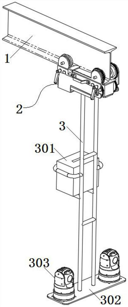
[0005] The purpose of the present invention is to provide an unmanned inspection trolley at the bottom of a super-large steel girder bridge. The inspection trolley installed on the I-beam and the control ball under the inspection trolley can realize the inspection of the bridge, which solves the problem of existing manual inspection. The problem of low detection efficiency and poor effect
At the same time, real-time detection can be carried out by checking the trolley, which solves the problem that the existing manual detection needs to be performed at a specific time at night and the working conditions are poor

Method used


Image

  • Unmanned inspection trolley for bottom of oversize steel beam bridge
  • Unmanned inspection trolley for bottom of oversize steel beam bridge
  • Unmanned inspection trolley for bottom of oversize steel beam bridge

Examples


Embodiment Construction

[0028] The following will clearly and completely describe the technical solutions in the embodiments of the present invention with reference to the accompanying drawings in the embodiments of the present invention. Obviously, the described embodiments are only some, not all, embodiments of the present invention. Based on the embodiments of the present invention, all other embodiments obtained by persons of ordinary skill in the art without creative efforts fall within the protection scope of the present invention.

[0029] In describing the present invention, it is to be understood that the terms "opening", "upper", "lower", "thickness", "top", "middle", "length", "inner", "surrounding" etc. Indicating orientation or positional relationship is only for the convenience of describing the present invention and simplifying the description, and does not indicate or imply that the components or elements referred to must have a specific orientation, be constructed and operated in a sp...


PUM


Abstract

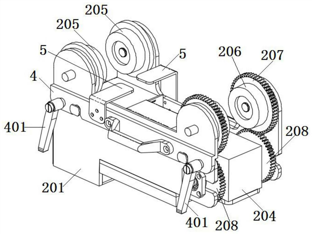
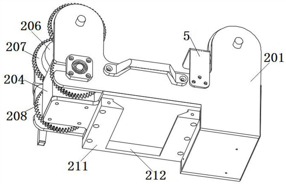
The invention discloses an unmanned inspection trolley for the bottom of an oversize steel beam bridge, and relates to the technical field of bridge detection. The trolley comprises an inspection trolley; the inspection trolley comprises a frame of a U-shaped structure; an electric appliance box, a motor and a T-shaped transmission box are fixed on the inner bottom surface of the frame; the two side walls of the frame are rotationally connected with single-side rail wheels and driving wheels; gear rings are arranged on the peripheral side surfaces of the driving wheels; the lower surface of the frame is detachably connected with a bracket; two output shafts of a T-shaped transmission box are both fixedly provided with gears meshed with the gear rings; the bracket is connected with a power supply; a mounting plate is fixed at the lower end of the bracket; a plurality of monitoring balls are arranged on the upper surface of the mounting plate. Through the inspection trolley walking on the I-shaped steel and the monitoring balls below the inspection trolley, the bridge detection is realized, and the detection efficiency and the detection effect are effectively improved. Meanwhile, real-time detection can be carried out through the inspection trolley, and the problems that existing manual detection needs to be carried out at specific time at night, and the working condition is poor are solved.

Description

technical field [0001] The invention belongs to the technical field of bridge detection, in particular to an unmanned inspection trolley at the bottom of a super-large steel girder bridge. Background technique [0002] In recent years, with the rapid development of my country's railways, railway construction equipment has steadily moved towards high-energy, high-efficiency, and high-tech direction; various constructions that used to rely on huge manpower have gradually changed to high-tech and labor-saving directions. At present, the inspection of the bottom of the steel girder bridge still relies on the inspectors to enter the inspection trolley and then move to the bottom of the bridge for inspection. The weather such as cross wind at the bottom of the bridge puts the personal safety of the inspectors at risk, and the inspection process needs to drive a large inspection trolley. It needs to consume a lot of labor cost and time cost. [0003] At the same time, manual inspe...

Claims


Application Information

Patent Timeline
Patent Type & Authority Applications(China)
IPC IPC(8): E01D19/10
CPCE01D19/106
Inventor 贡照华万乐山叶勇朱国靖齐龙飞韦康陈志远汪勇唐伟傲于强徐晟
Owner 合肥德泰科通测控技术有限公司
Learn More