A hybrid gas condensing heat exchanger

A condensing heat exchanger, hybrid technology, applied in steam/steam condensers, lighting and heating equipment, etc., can solve problems such as increasing costs, reducing heat transfer efficiency of heat exchangers, reducing economical efficiency of heat exchangers, etc., to achieve Improve heat conversion efficiency, prolong the heat absorption path of water flow, and ensure the effect of heat conversion efficiency

Active Publication Date: 2022-07-01
WUXI XIZHOU MACHINERY
View PDF6 Cites 0 Cited by
  • Summary
  • Abstract
  • Description
  • Claims
  • Application Information

AI Technical Summary

Problems solved by technology

[0004] At present, in the existing technology, most condensing heat exchangers use a single form of heat transfer tube. Fully adopting spiral heat transfer tubes will increase the cost and reduce the economy of the heat exchanger, and completely using straight-through heat transfer tubes will reduce the cost of the heat exchanger. heat conversion efficiency

Method used


Image

  • A hybrid gas condensing heat exchanger
  • A hybrid gas condensing heat exchanger
  • A hybrid gas condensing heat exchanger

Examples


Embodiment 1

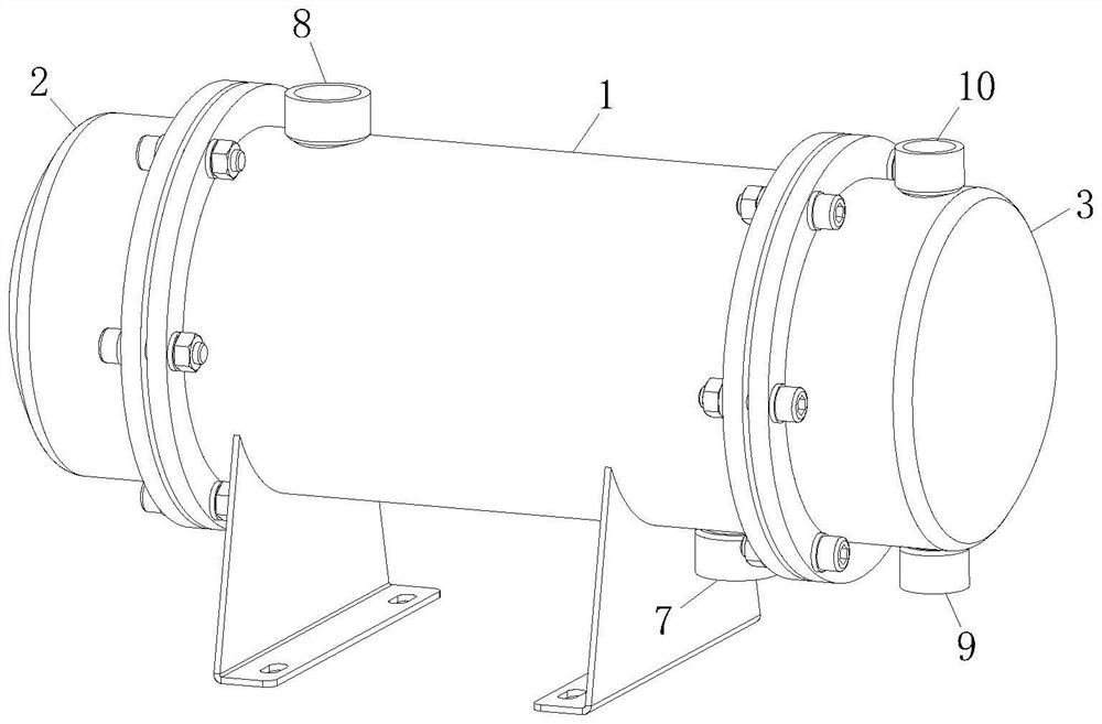
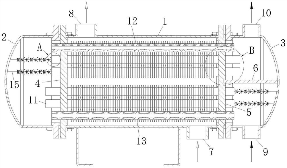
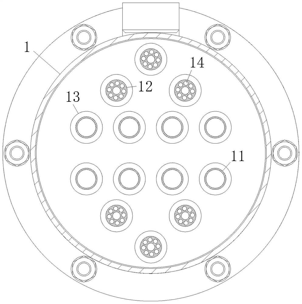
[0032] like Figure 1 to Figure 3 As shown, a hybrid gas-fired condensing heat exchanger according to an embodiment of the present invention includes a main casing 1; a left casing 2 and a right casing 3 are installed on both sides of the main casing 1; A left tube plate 4 is installed between the shell 1 and the left shell 2, and a right tube plate 5 is installed between the main shell 1 and the right shell 3; the right shell 3 is fixed with a partition plate 6; The main casing 1 is provided with an air inlet 7 and an air outlet 8; the right casing 3 is provided with a water inlet 9 and a water outlet 10; A straight heat pipe 11 and a plurality of spiral heat pipes 12, and the straight heat pipe 11 and the spiral heat pipe 12 communicate the left casing 2 with the right casing 3; A plurality of fins 13; the spiral heat pipe 12 is provided with a plurality of spiral holes 14; the high temperature flue gas enters the main casing 1 from the air inlet 7 at the bottom, and then f...

Embodiment 2

[0042] like Figure 8 As shown in the comparison example 1, another embodiment of the present invention is: an elastic film 34 is fixed between the No. 2 elastic sheet 33 and the inner wall of the installation pipe 28; the pipe wall of the installation pipe 28 is close to the elastic film 34 A guide hole 35 is opened at the position of the second magnet, and the guide hole 35 communicates with the elastic film 34; when the No. 2 magnetic block 23 squeezes the No. 2 elastic piece 33, the gas in the elastic film 34 inside will be ejected through the guide hole 35, It is sprayed on the surface of the fin 13 to blow off the condensed water adhering to the surface, which further improves the separation speed of the condensed water. After that, the No. 2 magnet block 23 is separated from the No. 2 spring piece 33, and the elastic film 34 is sucked through the guide hole 35. , this cycle.

[0043]Working principle: the high temperature flue gas enters the main casing 1 from the air ...


PUM


Abstract

The invention belongs to the technical field of heat exchangers, in particular to a hybrid gas-fired condensing heat exchanger, comprising a main casing, a left casing, a right casing, a left tube sheet and a right tube sheet; the main casing An air inlet and an air outlet are arranged on the upper part, and a water inlet and a water outlet are arranged on the right casing; a plurality of straight heat pipes and spiral heat pipes are installed between the left tube sheet and the right tube sheet; the straight heat pipes A number of fins are fixed on the outside; the spiral heat pipe is provided with a plurality of spiral holes; by setting a plurality of fins and a plurality of spiral holes in the spiral heat pipe, the heat absorption path of the water flow can be extended and the heat transfer can be increased. Compared with using a single heat pipe, it can not only ensure the heat conversion efficiency, but also improve the economy of the product and reduce the cost.

Description

technical field [0001] The invention belongs to the technical field of heat exchangers, in particular to a hybrid gas condensing heat exchanger. Background technique [0002] A heat exchanger is a device that transfers part of the heat of a hot fluid to a cold fluid, also known as a heat exchanger, so that heat is transferred from a fluid with a higher temperature to a fluid with a lower temperature, thereby heating the cold fluid. , Mainly used for domestic water or shopping mall heating, heat exchanger is a high-efficiency energy-saving equipment, but also one of the main equipment to improve energy utilization. [0003] A Chinese patent with publication number CN111023873B discloses a horizontal condensing heat exchanger, which includes a cylinder body, a descaling component, a heat exchange coil and a liquid spray head, and a heat exchange plate is installed inside the cylinder body. One side of the heat exchange plate is provided with a heat exchange coil, and the oute...

Claims


Application Information

Patent Timeline
Patent Type & Authority Patents(China)
IPC IPC(8): F28B1/02F28B9/04F28B9/08
CPCF28B1/02F28B9/04F28B9/08
Inventor 包建忠王正阳
Owner WUXI XIZHOU MACHINERY
Why Eureka
Try Eureka