Cylindrical heat exchanger

A heat exchanger, cylindrical technology, applied in the field of new heat exchangers, can solve the problems of not meeting the requirements of heat conversion efficiency of household heat exchangers, low heat conversion efficiency, large heat loss, etc., so as to reduce smoke exhaust Effects of heat loss, high heat transfer coefficient, and sufficient intake air

Active Publication Date: 2010-12-22
WUXI XIZHOU MACHINERY
View PDF6 Cites 4 Cited by
  • Summary
  • Abstract
  • Description
  • Claims
  • Application Information

AI Technical Summary

Problems solved by technology

However, the existing fuel-based heat exchangers have problems such as complex structure, large volume, low heat conversion efficiency, and large heat loss, which do not meet the heat conversion efficiency requirements of household heat exchangers.

Method used


Image

  • Cylindrical heat exchanger
  • Cylindrical heat exchanger
  • Cylindrical heat exchanger

Examples


Embodiment Construction

[0017] The present invention will be further described below in conjunction with specific drawings and embodiments.

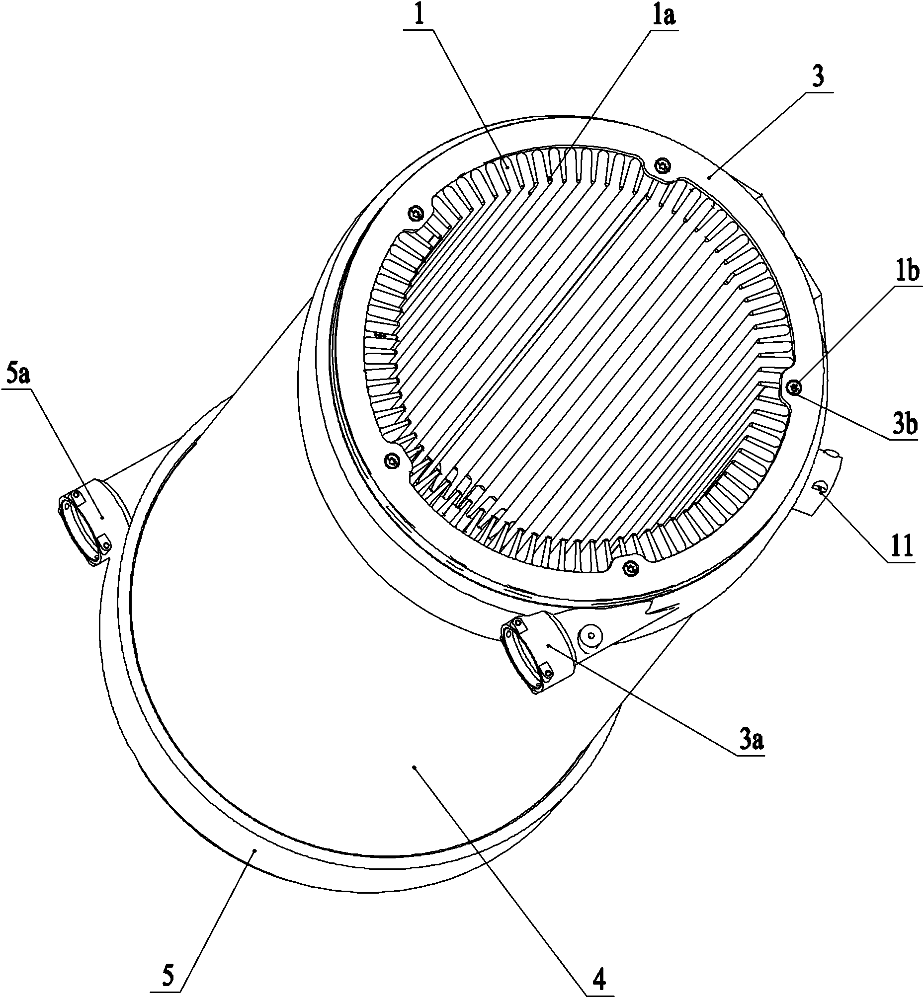
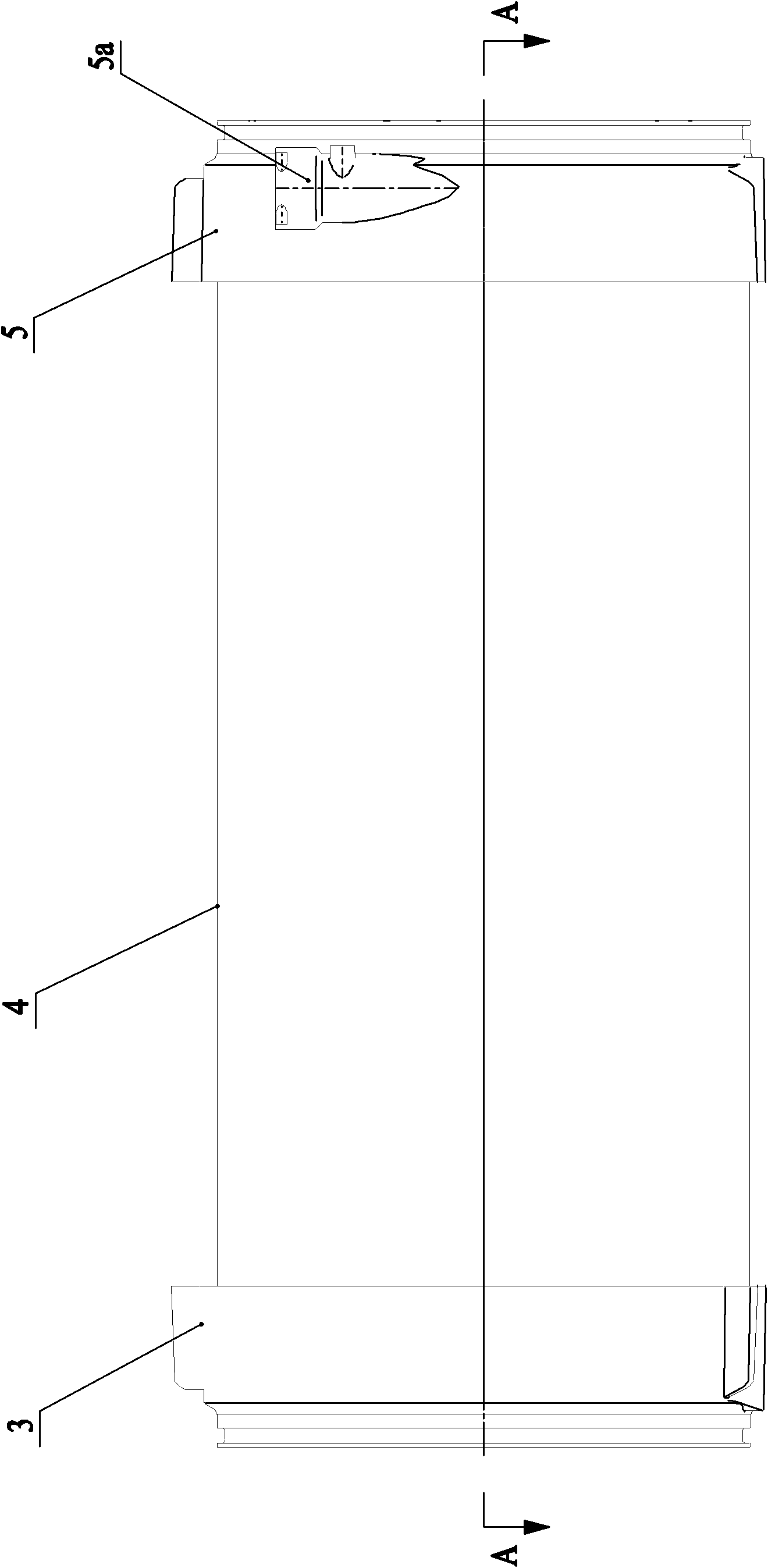
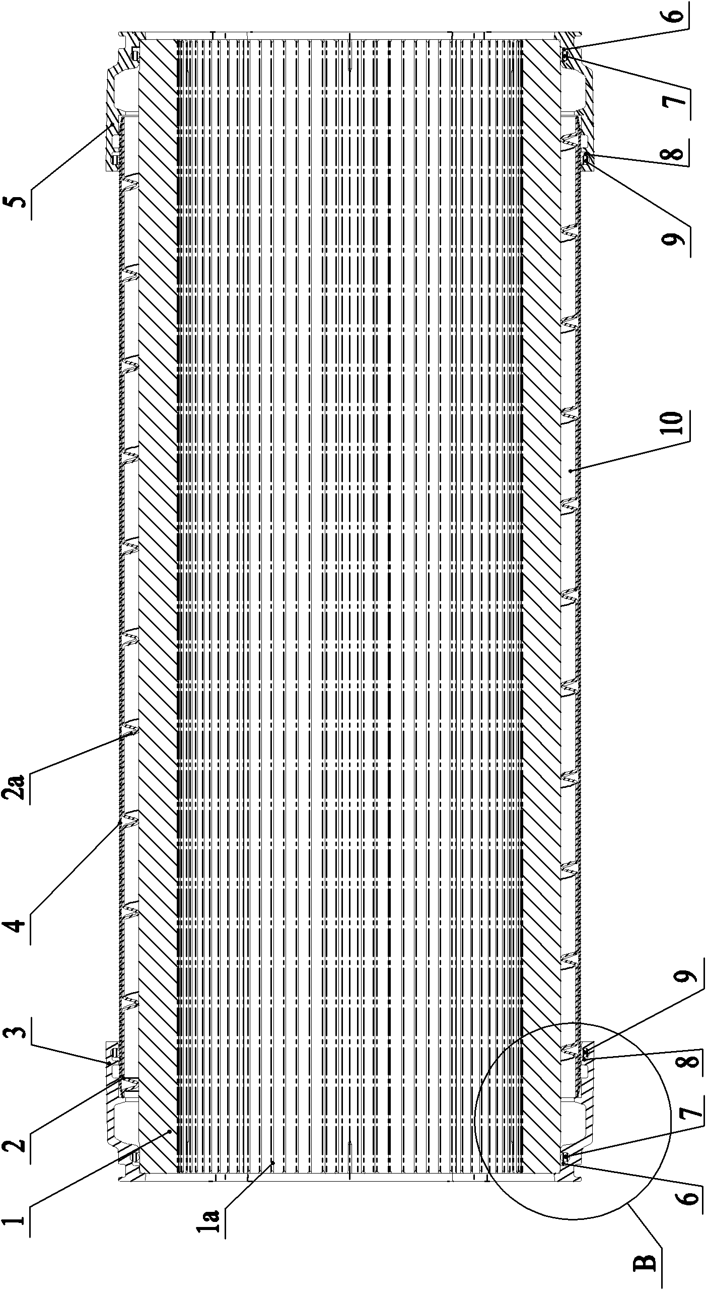
[0018] As shown in the figure: the cylindrical heat exchanger in the embodiment is mainly composed of a combustion chamber 1, a spiral sleeve 2, an upper end cover 3, a lower end cover 5, and a heat insulation reinforcement sleeve 4 and other components.

[0019] Such as Figure 1~Figure 3 As shown, the combustion chamber 1 is cylindrical with openings at both ends, and a certain number of strip-shaped fins 1a are evenly distributed on the inner peripheral wall of the combustion chamber 1, and the strip-shaped fins 1a are parallel to the cylindrical combustion chamber. In the axial direction of the cavity 1 , the two ends of the strip fins 1 a extend to the openings at both ends of the combustion cavity 1 . The spiral sleeve 2 is set on the combustion chamber 1, and the inner peripheral wall of the spiral sleeve 2 is provided with a convex helix 2a, and the in...


PUM


Abstract

The invention relates to a cylindrical heat exchanger, comprising a combustion cavity, a spiral screw sheel, an upper end cover and a lower end cover, wherein the combustion cavity is a cylinder with an opening at each of two ends thereof, strip fins are evenly distributed at the inner peripheral wall of the combustion cavity, the strip fins are parallel to the axial direction of the cylindrical combustion cavity, the two ends of the strip fins are extended to the openings of the two ends of the combustion cavity; the spiral screw sheel is sheathed on the combustion cavity, convex spiral lines are arranged on the inner peripheral wall of the spiral screw sheel, the inner edges of the convex spiral lines are in close integration with the outer wall surface of the combustion cavity, a spiral channel is formed between the outer wall of the combustion cavity and the inner wall of the spiral screw sheel; the upper end cover and the lower end cover are of cup shape respectively with an opening at the end face, respectively cover the two ends of the combustion cavity and the screw sheel and are fixed with the two ends of the combustion cavity and the spiral screw sheel by tight coupling; and the upper end cover is provided with a water inlet which is communicated with one end of the spiral channel, and the lower end cover is provided with a water outlet which is communicated with the other end of the spiral channel.The cylindrical heat exchanger of the invention features delicate and reasonable structure, convenient maintenance and cleaning, long service life, high thermal efficiency, energy conservation and durability.

Description

technical field [0001] The invention relates to a heat exchanger, in particular to a novel heat exchanger using high-efficiency fuel oil as a heating heat transfer medium. Background technique [0002] At present, there are various types of heat exchangers produced at home and abroad, which are widely used in heating equipment systems in homes, hotels, restaurants, hospitals, office buildings and other places. At present, the heat exchangers on the market are in different shapes, and their working principles are generally the same, that is, the fuel (coal, oil, gas) is burned in the combustion furnace to generate high-temperature flue gas, and the high-temperature flue gas flows through the heat exchanger to realize heat dissipation, Endothermic heat exchange step. At present, heat exchangers on the market can be divided into coal-fired, gas-fired and oil-fired heat exchangers according to the type of fuel. With the international development trend of energy saving, environm...

Claims


Application Information

Patent Timeline
Patent Type & Authority Applications(China)
IPC IPC(8): F24H1/26F24H9/02
Inventor 包建忠
Owner WUXI XIZHOU MACHINERY
Why Eureka
Try Eureka