
Electric energy collector of direct current machine room, electric energy collecting and monitoring equipment and electric energy collecting and monitoring method

A technology for power collection and DC cables, applied in instruments, measuring devices, electrical components, etc., can solve problems such as increased installation workload, increased cost, and inability to record real-time energy consumption in the computer room, achieving low monitoring costs and easy installation. Effect

Pending Publication Date: 2022-01-04
CHINA TELECOM CORP LTD
View PDF0 Cites 0 Cited by
  • Summary
  • Abstract
  • Description
  • Claims
  • Application Information

AI Technical Summary

Problems solved by technology

However, the manual monitoring method needs to manually test the current and voltage, and then use the current and voltage to calculate the energy consumption. This will inevitably lead to no way to record the real-time energy consumption of the computer room, which may cause huge monitoring errors.
When using ammeter monitoring, it is necessary to install a smart meter and a gateway. Since both the smart meter and the gateway need external power supply to work, it is necessary to provide additional power for the meter and the gateway at the same time, resulting in an increase in cost and installation. workload

Method used


Image

  • Electric energy collector of direct current machine room, electric energy collecting and monitoring equipment and electric energy collecting and monitoring method
  • Electric energy collector of direct current machine room, electric energy collecting and monitoring equipment and electric energy collecting and monitoring method
  • Electric energy collector of direct current machine room, electric energy collecting and monitoring equipment and electric energy collecting and monitoring method

Examples


Embodiment Construction

[0045] Example embodiments will now be described more fully with reference to the accompanying drawings. Example embodiments may, however, be embodied in many forms and should not be construed as limited to the embodiments set forth herein; rather, these embodiments are provided so that this disclosure will be thorough and complete, and will fully convey the concept of example embodiments to those skilled in the art. The same reference numerals in the drawings denote the same or similar structures, and thus their detailed descriptions will be omitted.

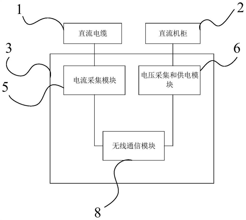
[0046] The present disclosure firstly provides an electric energy harvester for a DC machine room, such as figure 1 As shown, the power collector 3 of the DC machine room can collect the current value and voltage value of the DC machine room in real time through a single device. At the same time, the power collector 3 of the DC machine room can realize self-power supply, and only need to connect the power collector 3 of the D...


PUM


Abstract

The invention relates to an electric energy collector of a direct current machine room and an electric energy collecting and monitoring device and method, the direct current machine room is provided with a direct current cable and a direct current cabinet, the direct current cable is electrically connected with the direct current cabinet, and the electric energy collector of the direct current machine room comprises: a current collecting module which is connected with the direct current cable and the current collection module is used for collecting a current value flowing through the direct-current cable in real time; and a voltage acquisition and power supply module which is connected with the direct-current cabinet and is used for acquiring the voltage value of the direct-current cabinet in real time and supplying power to an electric energy acquirer of the direct-current machine room. The electric energy collector of the direct-current machine room can automatically collect the current value and the voltage value of the direct-current machine room, can realize self power supply, and can perform collection work without additionally connecting an external power supply.

Description

technical field [0001] The present disclosure relates to the technical field of energy consumption monitoring, and in particular to an electric energy collector for a DC machine room, an electric energy collection and monitoring device, and a method. Background technique [0002] Building an energy-saving and environment-friendly green computer room is the current development trend, but the doubled power consumption of equipment in the computer room has caused huge energy consumption in the computer room. Therefore, how to correctly evaluate the use and development trend of the computer room's energy consumption requires a Perfect and effective energy consumption monitoring and management system. [0003] At present, in this field, the commonly used energy consumption monitoring methods are manual monitoring and electric meter monitoring. However, the manual monitoring method needs to manually test the current and voltage, and then use the current and voltage to calculate t...

Claims


Application Information

Patent Timeline
IPC IPC(8): G01R22/06G01R15/20H02J13/00
CPCG01R22/063G01R15/202H02J13/00022Y02B90/20Y04S40/126
Inventor 蔡海立吴飞龙腾谭华
Owner CHINA TELECOM CORP LTD
Features
  • Generate Ideas
  • Intellectual Property
  • Life Sciences
  • Materials
  • Tech Scout
  • Unparalleled Data Quality
  • Higher Quality Content
  • 60% Fewer Hallucinations
Learn More