
Power electronic transformer with fault blocking function and use method thereof

A technology for power electronics and transformers, applied in transformers, fixed transformers, transformer/inductor shells, etc., can solve problems such as inability to quickly extinguish fire, limited scope or area of ​​fire extinguishing, and unsatisfactory fire extinguishing effect, so as to reduce damage. Effect

Pending Publication Date: 2022-01-04
中原豫安建设工程有限公司
View PDF1 Cites 0 Cited by
  • Summary
  • Abstract
  • Description
  • Claims
  • Application Information

AI Technical Summary

Problems solved by technology

However, once any of the modules is damaged and cannot work normally, overvoltage or overcurrent will still be generated in the circuit of the voltage transformer. Therefore, in order to avoid fires in the transformer, it is necessary to set up relevant fire extinguishing facilities. The application number is disclosed in the prior art It is CN201620394351.X, named as a power oil-immersed transformer with fire extinguishing function
In order to realize the automatic fire extinguishing of the transformer, an automatic dust fire extinguisher is installed on the base of the transformer. Although it can realize the automatic fire extinguishing function, because the nozzle direction of the fire extinguisher is fixed, the range or area of ​​fire extinguishing is limited, and sometimes it cannot Quickly extinguish the fire at the source of the fire, so the fire extinguishing effect is not ideal. In view of the above situation, the present invention proposes a power electronic transformer and method with fault blocking function

Method used


Image

  • Power electronic transformer with fault blocking function and use method thereof
  • Power electronic transformer with fault blocking function and use method thereof
  • Power electronic transformer with fault blocking function and use method thereof

Examples


Embodiment Construction

[0024] The following will clearly and completely describe the technical solutions in the embodiments of the present invention with reference to the accompanying drawings in the embodiments of the present invention. Obviously, the described embodiments are only some of the embodiments of the present invention, not all of them. The components of the embodiments of the invention generally described and illustrated in the figures herein may be arranged and designed in a variety of different configurations. Accordingly, the following detailed description of the embodiments of the invention provided in the accompanying drawings is not intended to limit the scope of the claimed invention, but merely represents selected embodiments of the invention. Based on the embodiments of the present invention, all other embodiments obtained by those skilled in the art without making creative efforts belong to the protection scope of the present invention.

[0025] In describing the embodiments o...


PUM


Abstract

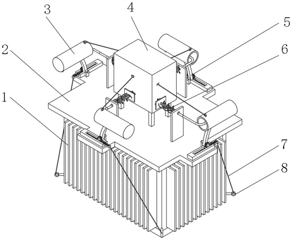
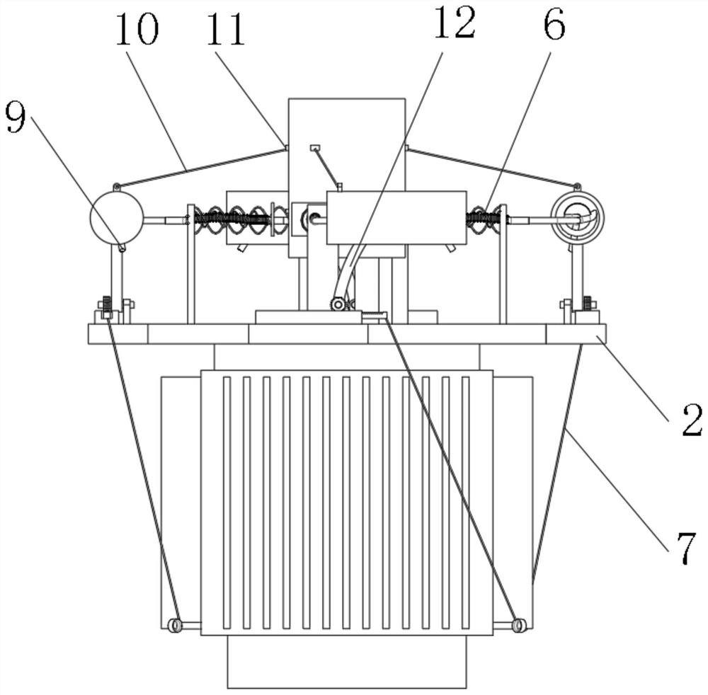
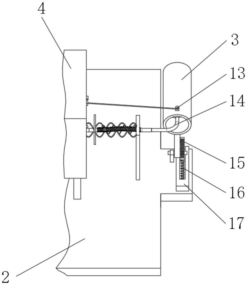
The invention discloses a power electronic transformer with a fault blocking function and a use method thereof. The power electronic transformer comprises a transformer body, a top plate is formed at the top of the transformer body, a storage box is fixed to the middle of the upper end face of the top plate, turnover mechanisms are installed on the peripheral edges of the top plate, and the tops of the turnover mechanisms are connected with containing barrels; a first hanging ring is welded to the periphery of the transformer body and connected with the driving end of the turnover mechanism through a first pull rope. A second hanging ring is welded to the top end of the containing barrel, pull blocks are arranged on the periphery of the storage box, the second hanging ring is connected with the pull blocks through second pull ropes, the pull blocks penetrate through the storage box in the horizontal direction and extend into the storage box, and a second pressing plate connected with the pull blocks in a clamped mode is arranged at the top in a cavity of the storage box. When the transformer body breaks down and catches fire, a fire source can be automatically extinguished in time, a circuit is cut off, damage is reduced, and the purpose of large-area fire extinguishment can be achieved through the containing barrel in the rotating state.

Description

technical field [0001] The invention belongs to the field of electrical equipment, and in particular relates to a power electronic transformer with a fault blocking function and a method thereof. Background technique [0002] During the working process of the transformer, sometimes there will be overvoltage or overcurrent phenomenon. Overvoltage or overcurrent will not only cause damage to electronic devices, but also cause fire in serious cases. Therefore, in order to prevent the above phenomenon from happening in the prior art, the Add DAB (dual active bridge structure) plus full bridge module and regenerative current blocking module to the electronic transformer module to solve the problem. However, once any of the modules is damaged and cannot work normally, overvoltage or overcurrent will still be generated in the circuit of the voltage transformer. Therefore, in order to avoid fires in the transformer, it is necessary to set up relevant fire extinguishing facilities. T...

Claims


Application Information

Patent Timeline
Patent Type & Authority Applications(China)
IPC IPC(8): H02H7/04H01F30/06H01F27/02H01F27/06A62C3/16
CPCH02H7/04H01F30/06H01F27/02H01F27/06A62C3/16
Inventor 顿士军杨博朱现平李学锋张帅李锐军刘灿芳杨金猛
Owner 中原豫安建设工程有限公司
Learn More