Single-phase Cuk variable-frequency AC-AC converter

A converter, single-phase technology, applied in the field of single-phase AC-AC converters, can solve the problems of low reliability, high cost, high loss, and achieve the effects of high power density, few switching devices, and high efficiency

Pending Publication Date: 2022-01-04
XIAMEN UNIV
View PDF4 Cites 0 Cited by
  • Summary
  • Abstract
  • Description
  • Claims
  • Application Information

AI Technical Summary

Problems solved by technology

However, the bulky DC bus energy storage capacitor and input filter lead to large size, high loss, high cost and low reliability of the indirect AC-AC converter

Method used


Image

  • Single-phase Cuk variable-frequency AC-AC converter
  • Single-phase Cuk variable-frequency AC-AC converter
  • Single-phase Cuk variable-frequency AC-AC converter

Examples


Embodiment 1

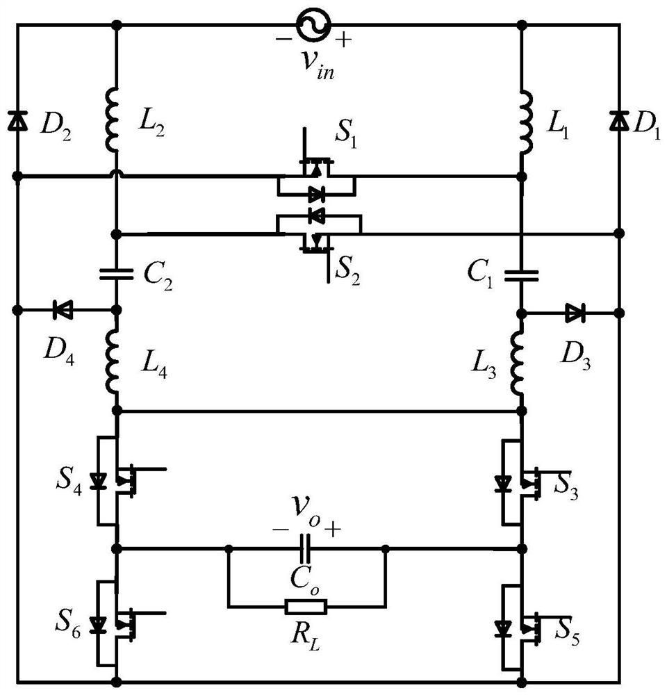
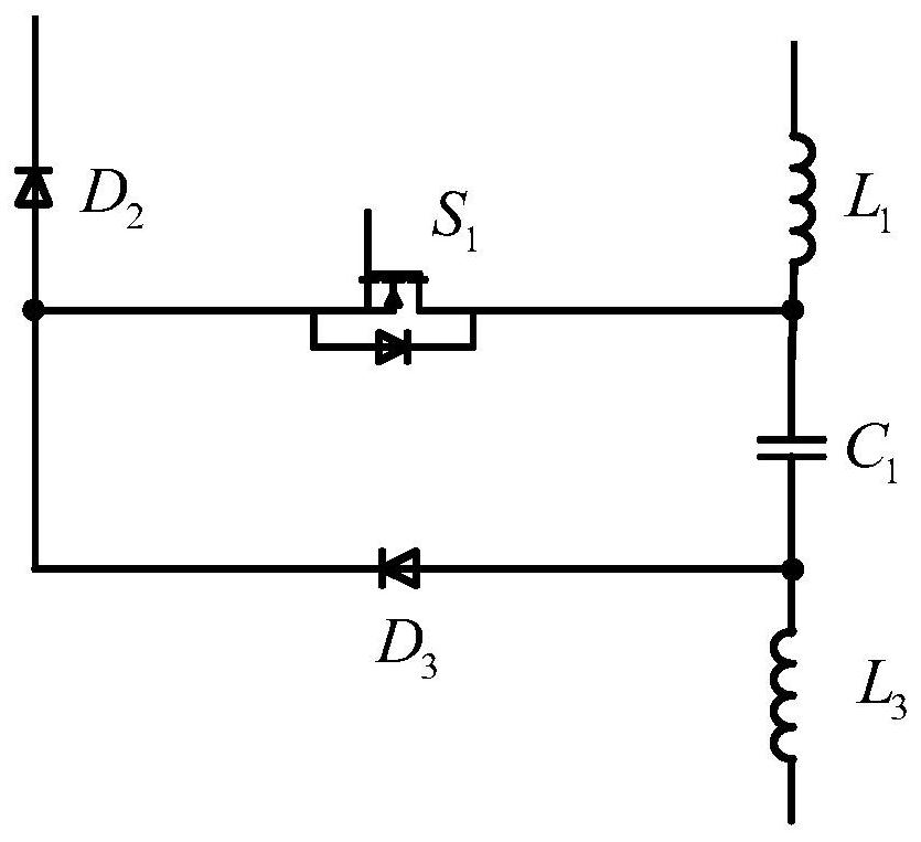
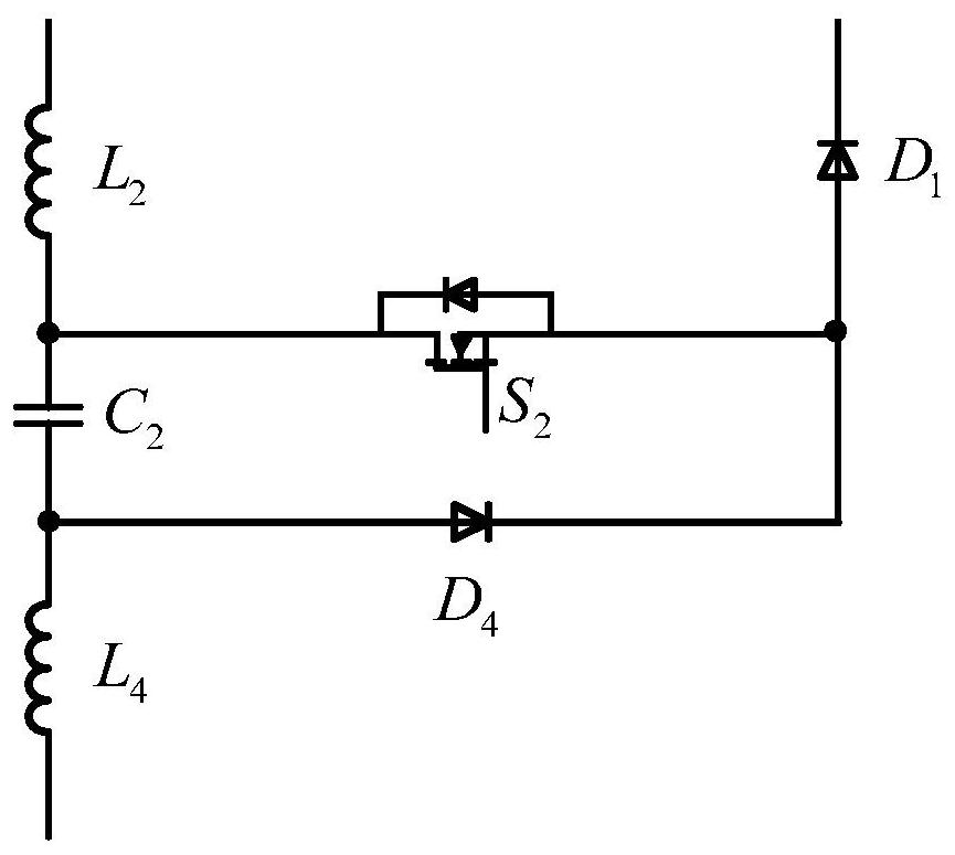
[0034] see figure 1 , the present invention includes an AC power supply, an input capacitor, a positive half-cycle voltage regulating unit, a negative half-cycle voltage regulating unit, an output polarity unit, an output capacitor and a load; the positive half-cycle voltage regulating unit consists of a first unidirectional switch S 1 , the first power inductor L 1 , the third power inductor L 3 , the first energy storage capacitor C 1 , the second diode D 2 and the third diode D 3 Composition; the negative half-cycle voltage regulating unit is composed of the second one-way switch S 2 , the second power inductor L 2 , the fourth power inductor L 4 , the second energy storage capacitor C 2 , the first diode D 1 and the fourth diode D 4 Composed; the output polarity unit is composed of a third one-way switch S 3 , the fourth one-way switch S 4 , the fifth one-way switch S 5 and the sixth unidirectional switch S 6 composition.

[0035] Specifically, see Figure 2...

Embodiment 2

[0048] see Figure 5 As shown in (b), in this embodiment, the converter is in the same-frequency output state, and the output and input are kept in the same phase, and the operation process of each circuit state is similar to that described in the first embodiment.

Embodiment 3

[0050] see Figure 5 As shown in (c), in this embodiment, the converter is in the 2-fold up-frequency output state. By changing the circuit operation state from positive half-cycle in-phase output to positive half-cycle inverting output at 1 / 4 input line cycle time, at 3 / 4 The operating state of the circuit is changed from negative half-cycle inverting output to negative half-cycle non-inverting output at the time of the line cycle, and the operation process of each circuit state is similar to that described in the first embodiment.

[0051] To sum up, the single-phase Cuk variable frequency AC-AC converter described in the present invention can realize buck-boost and variable-frequency AC voltage output, and the control strategy is simple and easy. Compared with the traditional AC-AC converter, it has It has the advantages of fewer switching devices, high power density, and high efficiency.


PUM


Abstract

According to a single-phase Cuk variable-frequency AC-AC converter disclosed by the invention, buck-boost and variable-frequency AC-AC conversion can be realized; the single-phase Cuk frequency conversion AC-AC converter is composed of a positive half-cycle voltage regulating unit, a negative half-cycle voltage regulating unit and an output polarity unit; the positive half-cycle voltage regulating unit and the negative half-cycle voltage regulating unit are completely symmetrical and each comprise a one-way switch, two inductors, a non-polar capacitor and two diodes; the output polarity unit comprises an H-bridge network formed by four one-way switches; by controlling the duty ratio of control signals of two high-frequency voltage regulating switches (S1 and S2), the amplitude of alternating-current output voltage can be regulated, and boost or buck output is realized; variable-frequency alternating-current output voltage can be obtained by adjusting a control signal time sequence of the four one-way switches of the output polarity unit; compared with a traditional AC-AC converter, the AC-AC converter has the advantages of few switching devices, high power density, high efficiency and the like, and is suitable for application occasions needing variable-voltage variable-frequency AC output.

Description

technical field [0001] The invention relates to a single-phase AC-AC converter, in particular to a single-phase Cuk frequency conversion AC-AC converter. Background technique [0002] Many industrial applications, such as adjustable speed drives, require an AC-AC power conversion system to generate a flexible output AC voltage. In order to realize AC energy conversion, the simplest way is through a direct AC-AC converter. The direct AC-AC converter is converted from the basic DC PWM switching converter. By replacing the unidirectional switching tube in its DC topology with a bidirectional switching tube, the converter can output the reverse phase during the negative half cycle of the AC input. Voltage, to achieve AC-AC conversion. The direct AC-AC converter adopts a single-stage energy conversion structure, which has the advantages of simple structure, small size, strong voltage regulation ability, and low cost. However, the direct AC-AC converter cannot achieve frequency ...

Claims


Application Information

Patent Timeline
Patent Type & Authority Applications(China)
IPC IPC(8): H02M5/293H02M5/297H02M1/42
CPCH02M5/293H02M5/297H02M1/42Y02B70/10
Inventor 何良宗徐鑫勇
Owner XIAMEN UNIV
Why Eureka
Try Eureka