Syringe with retractable needle head based on sliding connection
A technology of sliding connection and syringe, which is applied in the field of syringes, can solve the problems that the waste barrel is easy to be full, occupy the space of the waste barrel, waste storage space, etc., and achieve the effect of speeding up the preparation of medicines
- Summary
- Abstract
- Description
- Claims
- Application Information
AI Technical Summary
Problems solved by technology
Method used
Image

Examples
Embodiment 1
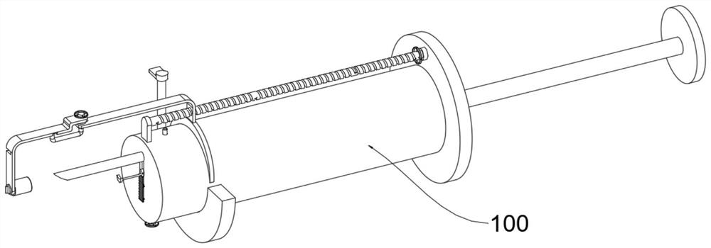
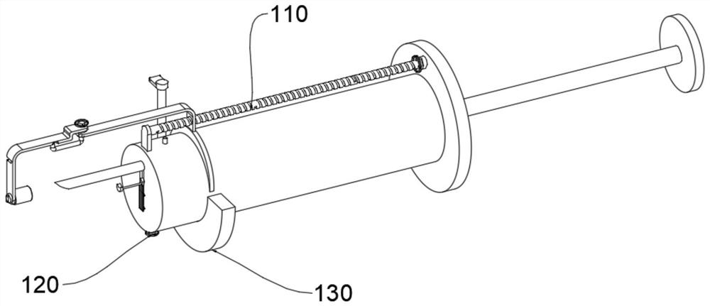
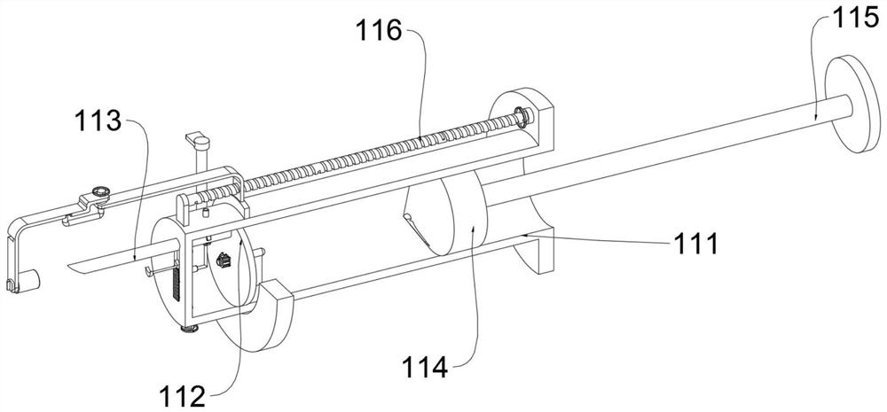
[0042] see Figure 1-Figure 6 As shown, the purpose of this embodiment is to provide a retractable syringe based on a sliding connection needle, including a syringe body 100, and the syringe body 100 at least includes:
[0043] The needle adjustment mechanism 110, the needle adjustment mechanism 110 includes a tube body 111, the inside of the tube body 111 is provided with a baffle 112, the inside of the baffle 112 is equipped with an injection needle 113, and the surface of the baffle 112 is provided with a liquid flow port through which the fluid can pass. 1121, the inside of the pipe body 111 is provided with a push plug 114, the surface of the push plug 114 is equipped with a push handle 115, the outside of the pipe body 111 is provided with an adjustment assembly 116, the adjustment assembly 116 includes a mounting plate 1161, the pipe body 111 and the mounting plate 1161 Adjusting screw 1162 is connected in rotation between them, the surface of adjusting screw 1162 is pr...
Embodiment 2
[0051] In order to improve the stable adaptability of the injection needle 113, the difference between this embodiment and Embodiment 1 is that please refer to Figure 7 Shown:
[0052] Wherein, the side wall of the tube body 111 is provided with a concave cavity 1111, and an electric push rod 1112 is installed inside the concave cavity 1111, and a fixed ring 1113 is connected to the top of the electric push rod 1112, and the fixed ring 1113 fits snugly with the surface of the injection needle 113 , wherein, two fixed rings 1113 are symmetrically arranged, and the two fixed rings 1113 are connected through rods, that is, after the position of the injection needle 113 is fitted and fixed by the fixing mechanism 120, the driving of the electric push rod 1112 makes the The fixing ring 1113 moves upwards along the inside of the concave cavity 1111, that is, the inside of the two fixing rings 1113 will fit the injection needle 113, which further strengthens the fixing of the inject...
Embodiment 3
[0055] In order to allow the tube body 111 to be mixed during the preparation of medicines, the difference between this embodiment and Embodiment 1 is that please refer to Figure 8-Figure 9 Shown:
[0056] Among them, to save the time of preparing medicine, the surface of the baffle 112 is provided with a rotating plate 1122, and the other end of the baffle 112 is provided with a driving motor, and the driving motor is rotatably connected with the rotating plate 1122. When preparing medicine, first insert the injection needle 113 into the product to extract the liquid medicine, and then push the push handle 115 to the outside of the tube body 111, so that the push plug 114 is pulled outward, that is, a negative pressure is generated inside the tube body 111, and the injection The needle 113 will gradually extract the medicinal liquid from the outside and place it inside the tube body 111. At this time, the drive motor is turned on by infrared remote control to make it work, a...
PUM
 Abstract
Description
Claims
Application Information
 - R&D
- Intellectual Property
- Life Sciences
- Materials
- Tech Scout
- Unparalleled Data Quality
- Higher Quality Content
- 60% Fewer Hallucinations
Browse by: Latest US Patents, China's latest patents, Technical Efficacy Thesaurus, Application Domain, Technology Topic, Popular Technical Reports.
© 2025 PatSnap. All rights reserved.Legal|Privacy policy|Modern Slavery Act Transparency Statement|Sitemap|About US| Contact US: help@patsnap.com