Space clamp clamping mechanism

A clamping mechanism and clamping mechanism technology, applied in clamping, manufacturing tools, metal processing mechanical parts, etc., can solve the problem that the clamp cannot be quickly positioned and clamped, and achieve the effect of reducing vibration, preventing rotation and facilitating fixing

Inactive Publication Date: 2022-01-07
上海槎南工贸发展有限公司
View PDF4 Cites 2 Cited by
  • Summary
  • Abstract
  • Description
  • Claims
  • Application Information

AI Technical Summary

Problems solved by technology

[0004] The present invention provides a space fixture clamping mechanism, which solves the defect that the existing fixture cannot be quickly positioned and clamped, and the top limit mechanism and the bottom limit mechanism are moved by the moving mechanism, which facilitates rapid positioning of both ends of the parts Fixed, by using the clamping mechanism to clamp the fixed parts, the rotating mechanism can adjust and change the position and angle of the parts, which is convenient for processing the device

Method used


Image

  • Space clamp clamping mechanism
  • Space clamp clamping mechanism
  • Space clamp clamping mechanism

Examples


Embodiment 1

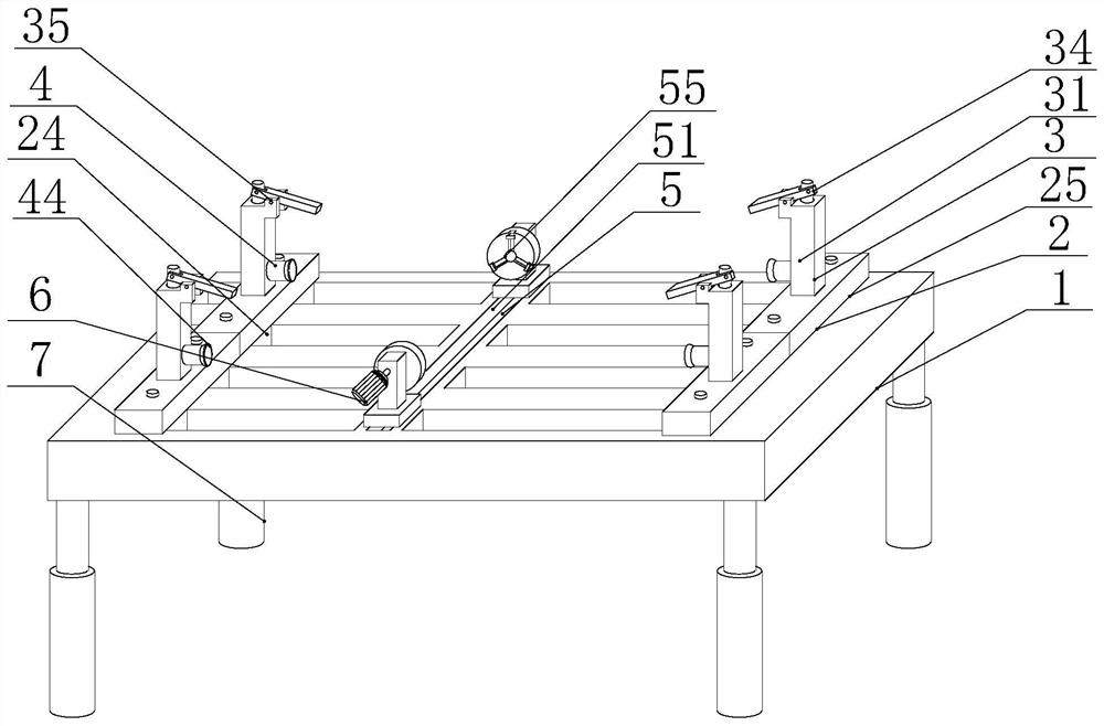
[0029] see figure 1 , a space fixture clamping mechanism of the present invention, including a working plate 1, a moving mechanism 2 is arranged on the top of the working plate 1, and the moving mechanism 2 drives the first movable block 23 and the second movable block 24 to move, so as to facilitate the clamping of parts At both ends, the top of the moving mechanism 2 is provided with a top limit mechanism 3, and the top position of the parts is limited by using the top limit mechanism 3. The positioning mechanism 4 limits the bottom position of the parts, and the four corners of the bottom of the working board 1 are fixedly connected with the support columns 7, which is convenient for the fixing and stability of the working board 1.

[0030] Existing fixtures can only clamp specific parts, but cannot achieve three-dimensional clamping, restrict each end of the parts, and prevent parts from moving. By using top clamping, lateral clamping at both ends and vertical clamping at ...

Embodiment 2

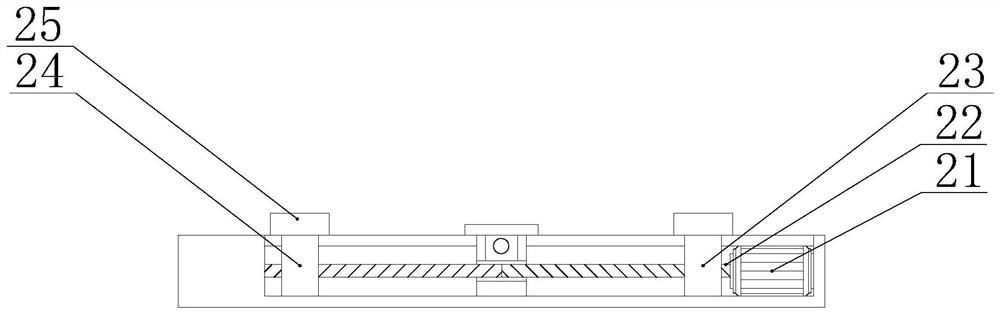
[0033] see Figure 2-4 , in order to quickly move the top limit mechanism 3 and the bottom limit mechanism 4, instead of manually clamping and fixing the parts, it is convenient for the fast fixing and limit of the parts. The moving mechanism 2 includes a first stepping motor 21, a first stepping motor 21 Fixedly connected to one end of the inner cavity of the working plate 1, the output end of the first stepping motor 21 is fixedly connected to a bidirectional threaded rod 22, and the bidirectional threaded rod 22 is provided with threads in opposite directions from the middle to both ends, and the bidirectional threaded rod 22 is close to the first step One end of the motor 21 is screwed with the first movable block 23, and the two-way threaded rod 22 is screwed with the second movable block 24 away from the first stepper motor 21. The first movable block 23 and the second movable block 24 are symmetrical to each other, so that The stepping motor 21 drives the first movable ...

Embodiment 3

[0038] see Figure 5 and Image 6 , in order to facilitate the clamping of the other two ends of the parts, the parts are completely fixed, and the parts are prevented from moving in any direction. There are two second hydraulic rods 52 that are symmetrically connected to each other, and the output end of the second hydraulic rod 52 is fixedly connected with an output rod 53, and a first pull block 54 and a second pull block 56 pass through the output rod 53, so as to facilitate the first Two hydraulic rods 52 drive the first pull block 54 and the second pull block 56 to move, and one end of the first pull block 54 is rotatably connected with a handle, and the handle passes through the end of the first pull block 54 and is threadedly connected with a three-jaw chuck 55, which is convenient for clamping and fixing on the part, preventing it from moving.

[0039] In this embodiment, in order to prevent the first pulling block 54 and the second pulling block 56 from detaching f...


PUM


Abstract

The invention provides a space clamp clamping mechanism. The mechanism comprises a working plate, a moving mechanism is arranged at the top of the working plate, a top limiting mechanism is arranged at the top of the moving mechanism, a bottom limiting mechanism is arranged at the end, away from the top limiting mechanism, of the moving mechanism, a clamping mechanism is arranged between the working plate and the moving mechanism, and a rotating mechanism is arranged at one end of the top of the clamping mechanism. The mechanism has the advantages that through movement of the top limiting mechanism and the bottom limiting mechanism, the two ends of a part can be conveniently and rapidly positioned and fixed. By using the clamping mechanism and the rotating mechanism, the positions and angles of the part can be adjusted and changed, and the mechanism can be conveniently machined. The pressure on the part is reduced through a first spring, vibration during machining is reduced, and damage caused by too large stress on the part is prevented through the trapezoidal extrusion end. A second spring extrudes an extension rod to move, so that the extension rod is conveniently inserted into a fixed disc, and the output end of a second stepping motor is conveniently fixed and prevented from rotating.

Description

technical field [0001] The invention relates to the technical field of fixture equipment, in particular to a space fixture clamping mechanism. Background technique [0002] Fixtures are generally used in the field of mechanical processing. The parts to be processed can be clamped and fixed by the fixture, so that the parts are in the correct position, and the parts can be moved to the proper position quickly, conveniently and safely. [0003] The existing clamps are generally driven manually, and the efficiency of clamping parts is relatively low, and the clamping limit force is not strong enough to quickly clamp the parts. The existing clamps can only clamp one end of the parts. As a result, the other end of the component is easy to loosen during processing, which affects the processing result. The existing device cannot rotate the component and process the component at different angles. Contents of the invention [0004] The present invention provides a space fixture cl...

Claims


Application Information

Patent Timeline
Patent Type & Authority Applications(China)
IPC IPC(8): B23Q3/06B23Q11/00
CPCB23Q3/06B23Q11/0032
Inventor 徐佳时
Owner 上海槎南工贸发展有限公司
Why Eureka
Try Eureka