Supercharge Your Innovation With Domain-Expert AI Agents!

Water plant filter tank control system

A control system and filter technology, applied in the general control system, control/regulation system, water treatment parameter control, etc., can solve the problem of water quality and water supply decline, failure to obtain filtering effect, and timely response to failure processing And other issues

Pending Publication Date: 2022-01-07
贵阳北控水务有限责任公司
View PDF6 Cites 0 Cited by
  • Summary
  • Abstract
  • Description
  • Claims
  • Application Information

AI Technical Summary

Problems solved by technology

[0003] Sand washing in existing water plant filters is still carried out manually. This mode has the following problems: 1. Low efficiency. Sand washing in filters is a closed-loop system. Different equipment needs to be invested in each link according to a certain sequence. There needs to be corresponding equipment start-stop control. In the manual method, each link needs to be on duty. Since the equipment in each link is far apart, the traditional method is to contact the equipment in each link by telephone, so that The efficiency of sand washing is greatly reduced
[0004] 2. The lag in the handling of sand washing accidents. In the manual washing mode, if there is a problem with a certain equipment, the sand washing process needs to be interrupted. Due to the lag of the communication method, the fault handling cannot be responded in time, which will cause other problems. unforeseen event
[0005] 3. The sand washing is not thorough. In the manual method, due to the lack of responsibility of some operators, the sand washing in the filter tank is not thorough, which leads to a decline in water quality and water supply.
[0006] 4. The high-efficiency filtration of the filter cannot be guaranteed. The standard state of the filter is to maintain a constant water level for filtration, but manual methods cannot be achieved, because it is a dynamic and constant adjustment process, which eventually leads to a low-efficiency filter. state, the best filtering effect cannot be obtained, and the equipment energy consumption increases due to frequent sand washing

Method used


Image

  • Water plant filter tank control system

Examples


Embodiment Construction

[0021] The specific embodiments of the present invention will be further described below in conjunction with the accompanying drawings. It should be noted here that the descriptions of these embodiments are used to help understand the present invention, but are not intended to limit the present invention. In addition, the technical features involved in the various embodiments of the present invention described below may be combined with each other as long as they do not constitute a conflict with each other.

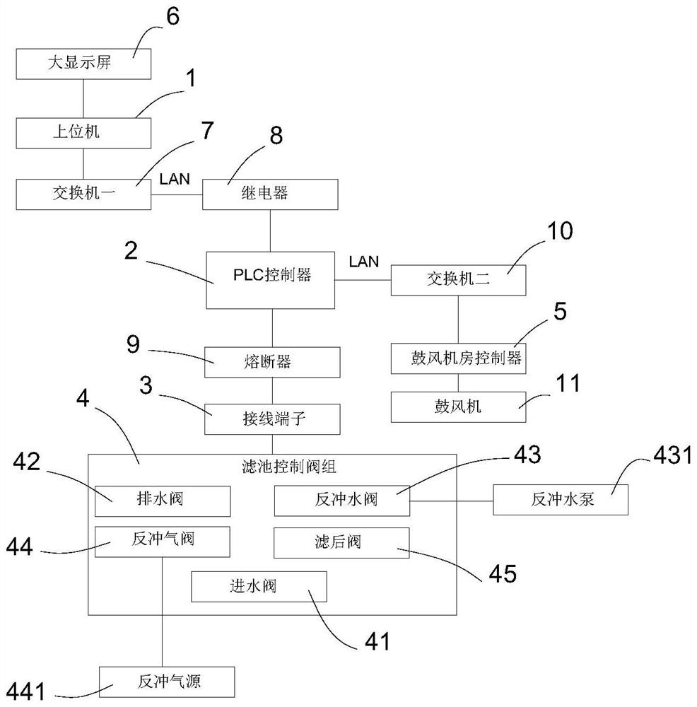
[0022] refer to figure 1 , a water plant filter control system of the present invention, comprising a host computer 1, the host computer 1 is connected to a PLC controller 2 through a LAN, and realizes data interaction, and the PLC controller 2 communicates with the filter tank through a connection terminal 3 The control valve group 4 is connected, and the PLC controller 2 is connected with the blower room controller 5 through LAN to realize data interaction. The PLC c...


PUM


Abstract

The invention relates to the technical field of control equipment, in particular to a water plant filter tank control system. The water plant filter tank control system comprises an upper computer, the upper computer is connected with a PLC through an LAN and achieves data interaction; the PLC is connected with a filter tank control valve set through a wiring terminal, and the PLC is connected with an air blower room controller through the LAN and achieves data interaction. Control substations among the upper computer, the filter tank control valve group and the air blower room controller are built by utilizing the PLC, a communication network is formed by the upper computer I, the upper computer II and an LAN, then a larger communication loop is formed by the communication network, a backflushing water pump, a backflushing air source and the like, and then the communication loop is connected with data of the air blower controller; finally, field data are transmitted to the upper computer arranged in the water plant through the LAN, the upper computer transmits the data to a large display screen, and large-screen display of real-time data information is achieved.

Description

technical field [0001] The invention relates to the technical field of control equipment, in particular to a water plant filter control system. Background technique [0002] The filter is an extremely important part of the production process of the water plant. Its filtering effect will seriously affect the water quality index of the factory. The sand washing of the filter is the most important thing in the filter process. The filter sand washing system is usually composed of several major processes such as air flushing, water flushing, air-water mixed flushing, sewage recovery, and pneumatic valve drive. [0003] Sand washing in existing water plant filters is still carried out manually. This mode has the following problems: 1. Low efficiency. Sand washing in filters is a closed-loop system. Different equipment needs to be invested in each link according to a certain sequence. There needs to be corresponding equipment start-stop control. In the manual method, each link nee...

Claims


Application Information

Patent Timeline
Patent Type & Authority Applications(China)
IPC IPC(8): C02F1/00G05B19/05
CPCC02F1/001G05B19/054C02F2209/005
Inventor 杨徐春李松江治伟华志勇闵嘉涛关好然
Owner 贵阳北控水务有限责任公司
Features
  • R&D
  • Intellectual Property
  • Life Sciences
  • Materials
  • Tech Scout
  • Unparalleled Data Quality
  • Higher Quality Content
  • 60% Fewer Hallucinations
Learn More