
Tension and compression force measuring support

A force measuring and seat plate technology, which is applied to measuring devices, force/torque/work measuring instruments, bridge parts, etc., can solve the problems of the overall height of the bearing, the huge difference in the structure form, and the complex structure, and achieves the lightness of the device. , Simple structure, large space effect

Active Publication Date: 2022-01-07
LUOYANG SUNRUI SPECIAL EQUIP
View PDF8 Cites 1 Cited by
  • Summary
  • Abstract
  • Description
  • Claims
  • Application Information

AI Technical Summary

Problems solved by technology

However, the existing tension-compression bearings basically do not have force-measuring functions. Traditional force-measuring bearings often use pressure sensors for pressure measurement, which cannot achieve tension measurement. However, the structure of tension-compression bearings is very different from traditional bearings. It is not a matter of replacing sensors. Capable of measuring force
Multiple sensors are used to monitor tension and pressure separately, resulting in an increase in the overall height of the support and a complex structure. Therefore, it is urgent to invent a tension-compression force-measuring support with a simple structure and clear force.

Method used


Image

  • Tension and compression force measuring support
  • Tension and compression force measuring support
  • Tension and compression force measuring support

Examples


Embodiment 1

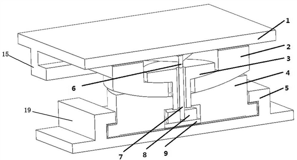
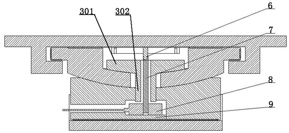
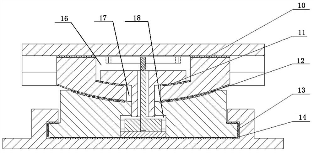
[0042] Embodiment 1 provides a schematic diagram of the structure of the tension-compression force-measuring bearing, see figure 1 , figure 2 , image 3 and Figure 4 , it is mainly composed of top seat plate 1, upper seat plate 2, middle shaft member 3, lower seat plate 4, and base plate 5. The force measuring part consists of force measuring universal joint 6, dowel rod 7, pull The pressure sensor 8 is composed of a sensor base 9.

[0043] The friction pairs required for the planar sliding of the tension-compression support structure are mainly composed of the upper seat plate planar sliding friction pair 10 and the lower seat plate planar sliding friction pair 14 . The rotation is composed of the center spherical friction pair 11 of the upper seat plate and the concave spherical friction pair 12 of the lower seat plate. The sliding friction pair 13 of the limiting device plays the role of transmitting the tensile stress, and also plays the role of reducing the rotating...


PUM


Abstract

A tension and compression force measuring support comprises a top seat plate, an upper seat plate, a lower seat plate, a bottom seat plate and a tension and compression force measuring device. The top seat plate, the upper seat plate, the lower seat plate and the bottom seat plate are axially symmetrically arranged in sequence from top to bottom. The tension and compression force measuring device comprises a force measuring universal joint, a dowel bar, a middle shaft piece and a tension and compression sensor, the middle shaft piece is composed of a plate-shaped section and a cylindrical section, the bottom surface of the plate-shaped section is a spherical surface matched with the cavity bottom of the first cavity of the upper seat plate, the cylindrical section penetrates through the second cavity and then is fixed to the lower seat plate, a gap is formed between the cylindrical section and the cavity wall of the second cavity, the middle shaft piece is provided with a through hole penetrating through the middle shaft piece, the dowel bar penetrates through the through hole and is not in contact with the through hole, one end of the dowel bar is fixedly connected with a tension and compression sensor, the tension and compression sensor is fixed in a third cavity, and the other end of the dowel bar is hinged to a force measuring universal joint arranged in the first cavity. According to the support, the stress of a central shaft is used as a force measuring part, and the stress condition of the support is monitored by the single tension and compression sensor through the structural design of the universal joint-the dowel bar.

Description

technical field [0001] The invention relates to the technical field of bearings, in particular to a tension-compression force-measuring bearing. Background technique [0002] With the rapid development of passenger dedicated lines, high-speed railways, expressways and urban interchanges in China, the structural types of bridges are showing a trend of diversification, and girder types with floating structures such as oblique girders, curved girders, and cable-stayed bridges have begun to appear in large numbers. Under the influence of temperature creep, wind load, self-bending moment and other factors, these bridge structures will generate tension opposite to the direction of gravity on some bridge nodes. The use of tension and compression bearings is a simple and economical structural measure. With the introduction of concepts such as smart transportation and structural health monitoring, real-time monitoring of important bridges to ensure transportation safety and prevent m...

Claims


Application Information

Patent Timeline
Patent Type & Authority Applications(China)
IPC IPC(8): E01D19/04G01L5/00
CPCE01D19/04G01L5/00
Inventor 李宗源郑娜杨卫锋宋建平顾海龙贾立志
Owner LUOYANG SUNRUI SPECIAL EQUIP
Learn More