Flap stopper for a rotatable flap

A technology of stopper and damper, used in engine components, vehicle components, lift valves, etc., can solve problems such as high cost and achieve the effect of high heat resistance and low density

Active Publication Date: 2022-01-07
MAHLE INT GMBH
View PDF7 Cites 0 Cited by
  • Summary
  • Abstract
  • Description
  • Claims
  • Application Information

AI Technical Summary

Problems solved by technology

For this reason, the above-mentioned intermediate member is made of a harder plastic, such as polyamide, which leads to higher costs even though a higher resistance can be obtained

Method used


Image

  • Flap stopper for a rotatable flap
  • Flap stopper for a rotatable flap
  • Flap stopper for a rotatable flap

Examples


Embodiment Construction

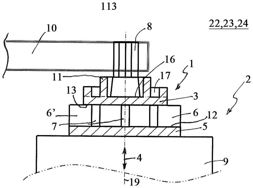
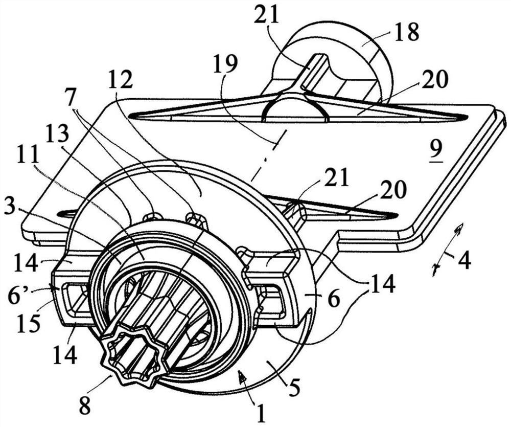
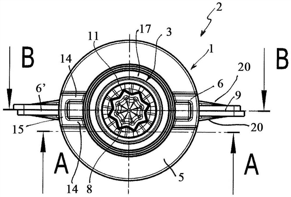
[0026] according to Figure 1 to Figure 5A damper stop 1 of a rotatable damper 2 for controlling an air flow according to the invention has a disc-shaped support support plate 3 and a disc-shaped stop support plate 5 spaced therefrom in the axial direction 4 . The two stop elements 6 , 6 ′ are thus arranged on the stop support plate 5 , wherein a connecting rib 7 is additionally arranged or extends between the carrier support plate 3 and the stop support plate 5 . According to the invention, the carrier support plate 3 , the stop support plate 5 , the stop elements 6 , 6 ′ and the connection rib 7 are now formed as a one-piece plastic injection molded part, in particular even from the same plastic. By means of the bearing support plate 3 and the stop support plate 5 , due to their disk-shaped design, relatively high torques can be introduced into the axial extension 8 via the stop elements 6 , 6 ′ and thus simultaneously provided by The stop elements 6, 6' are formed from a l...


PUM


Abstract

The invention relates to a flap stop (1) for a rotatable flap (2) for controlling an air flow. The flap stopper comprises a circular bearing support disc (3) and a circular stopper support disc (5) which is spaced apart therefrom in the axial direction (4), wherein stop elements (6, 6') are arranged on the stopper support disc (5), connecting ribs (7) are arranged between the bearing support disc (3) and the stopper support disc (5), and the bearing support disc (3), the stopper support disc (5), the stop elements (6, 6') and the connecting ribs (7) are formed as a one-piece plastic injection molded part. Under the influence of an actuator torque, the stress of a flap material can be distributed such that no residual (plastic) shape change is caused in the flap (2).

Description

technical field [0001] The invention relates to a damper stop for a rotatable damper for controlling air flow. The invention also relates to a rotatable damper for controlling air flow, comprising a damper blade and such a damper stop. The invention also relates to an air control device comprising such a damper and an air conditioning system comprising such an air control device. Background technique [0002] Damper controls in air conditioning systems of motor vehicles are well known and generally have a rotatable damper which is adjusted by rotation between a closed position and an open position. However, a direct drive of such a flap by means of an actuator comprising an integral flap stop can thus generate relatively high torsional stresses in the flap-side actuator receptacle and in the region of the flap stop. For this purpose, a so-called intermediate component is often used, which is made of a more durable material than the damper, for example a more durable plasti...

Claims


Application Information

Patent Timeline
Patent Type & Authority Applications(China)
IPC IPC(8): F16K1/22F16K1/32F16K1/48F16K1/50
CPCF16K1/22F16K1/32F16K1/50B60H2001/00707B60H1/00678B60H1/00685B60H1/00564B60H2001/3471B60H1/26
Inventor 马克·弗拉士迈克尔·科莫斯基霍尔格·雷克斯
Owner MAHLE INT GMBH
Why Eureka
Try Eureka