A transmission box for a tiller

A technology of micro-tiller and transmission box, which is applied in the directions of transmission box, transmission device parts, transmission device control, etc., can solve the problems of inability to control the driving force, limited application scope, difficult manufacturing, etc., so as to avoid adverse consequences, Wide range of applications, easy installation and production

Inactive Publication Date: 2017-06-09
HUNAN CHUANGNIU AGRI MACHINERY
View PDF7 Cites 0 Cited by
  • Summary
  • Abstract
  • Description
  • Claims
  • Application Information

AI Technical Summary

Problems solved by technology

[0004] The purpose of the present invention is to provide a transmission box for a micro-tiller to solve the technical problems that the existing micro-tiller is difficult to design and manufacture, the driving force cannot be controlled, and the application range is limited due to excessive driving force

Method used


Image

  • A transmission box for a tiller
  • A transmission box for a tiller
  • A transmission box for a tiller

Examples


Embodiment Construction

[0032] The embodiments of the present invention will be described in detail below with reference to the accompanying drawings, but the present invention can be implemented in many different ways defined and covered by the claims.

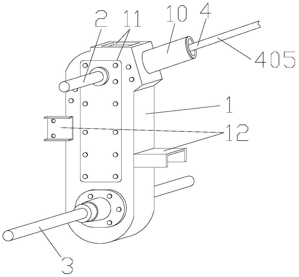
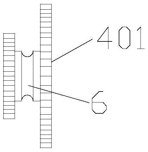
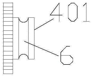
[0033] figure 1 It is a structural schematic diagram of a transmission box for a tiller in a preferred embodiment of the present invention; figure 2 is one of the structural schematic diagrams of the gear set in the preferred embodiment of the present invention; image 3 It is the second structural diagram of the gear set in the preferred embodiment of the present invention; Figure 4 is the third structural schematic diagram of the gear set in the preferred embodiment of the present invention; Figure 5 is a schematic structural view of the spline shaft of the preferred embodiment of the present invention; Image 6 It is a structural schematic diagram of an adjusting plug in a preferred embodiment of the present invention; Figure 7 It is a st...


PUM


Abstract

The invention discloses a transmission box for a micro tilling machine. The transmission box comprises a shell (1), a driving shaft (2) and a transmission shaft (3) are mounted on the shell (1) and are in mutual meshing, connection and transmission through a gear, a control mechanism (4) used for adjusting axial position of a gear on the driving shaft (2) to control rotating speed and rotating direction of the transmission shaft (3) is arranged on the driving shaft (2), and a stopper (5) used for stopping rotation is mounted on the driving shaft (2). The transmission box is a transmission box with a differential, so that the rotating speed can be changed easily, changing of the rotating direction and controlling of advancing and retreating can be realized, the micro tilling machine with the transmission box is enabled to be suitable for people of any age group, with any physical strength and different in proficiency to use, thereby being wider in application range, and the micro tilling machine is enabled to timely stop under any emergency to avoid various unfavorable consequences in the process of running.

Description

technical field [0001] The invention relates to the technical field of agricultural tillage equipment, in particular to a transmission box for a tiller. Background technique [0002] With the development of science and technology, more and more agricultural machinery has been popularized, and various new types of agricultural farming equipment have emerged. [0003] At present, there are many types of miniature cultivators (abbreviated as micro-cultivators), but most of the existing micro-cultivators use complex drive mechanisms or complex drive methods, which makes the design and manufacture more difficult, and the cost is also rising; and the drive mechanism cannot Very good control results in excessive driving force, which is not suitable for people with too little physical strength and limits the scope of application. Contents of the invention [0004] The purpose of the present invention is to provide a transmission box for a micro tillage machine to solve the techni...

Claims


Application Information

Patent Timeline
Patent Type & Authority Patents(China)
IPC IPC(8): F16H57/02F16H63/30F16H57/025F16D63/00A01B71/06
CPCA01B71/06F16H57/02F16H63/30
Inventor 张卓
Owner HUNAN CHUANGNIU AGRI MACHINERY
Why Eureka
Try Eureka