Anti-whipping energy dissipation limiting device with built-in viscous damper

A technology of limiting device and viscous damping, applied in the direction of coil spring, non-rotation vibration suppression, pipe/pipe joint/pipe fitting, etc., can solve the displacement, fixed end and pipe damage that cannot limit the high-energy pipe to the direction of the fixed end Problems such as energy dissipation capacity, inability to limit circumferential rotation and longitudinal displacement, etc.

Pending Publication Date: 2022-01-07
CHINA ENERGY ENG GRP GUANGDONG ELECTRIC POWER DESIGN INST CO LTD
View PDF0 Cites 0 Cited by
  • Summary
  • Abstract
  • Description
  • Claims
  • Application Information

AI Technical Summary

Problems solved by technology

[0006] The technical problem to be solved by the present invention, that is, the purpose of the present invention, is to solve the existence of U-shaped hoop structure anti-swing parts in the prior art, which can only limit the radial displacement of the high-energy pipeline, cannot limit the circumferential rotation and longitudinal displacement, and cannot limit the high-energy pipeline. The displacement of the pipe in the direction of the fixed end will easily cause damage to the fixed end and the pipe and the low energy dissipation capacity. A kind of anti-swing energy dissipation limit device for high-energy pipes is provided, which has the ability to limit the diameter of high-energy pipes. It has prominent substantive features and significant technological progress, such as limiting the circumferential rotation and longitudinal displacement, limiting the displacement of the high-energy pipeline to the direction of the fixed end, preventing damage to the fixed end and the pipeline, and high energy consumption capacity.

Method used


Image

  • Anti-whipping energy dissipation limiting device with built-in viscous damper
  • Anti-whipping energy dissipation limiting device with built-in viscous damper
  • Anti-whipping energy dissipation limiting device with built-in viscous damper

Examples


specific Embodiment 1

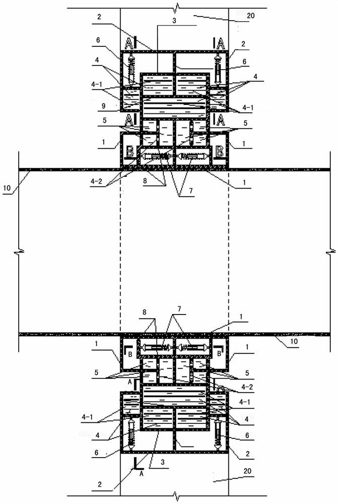
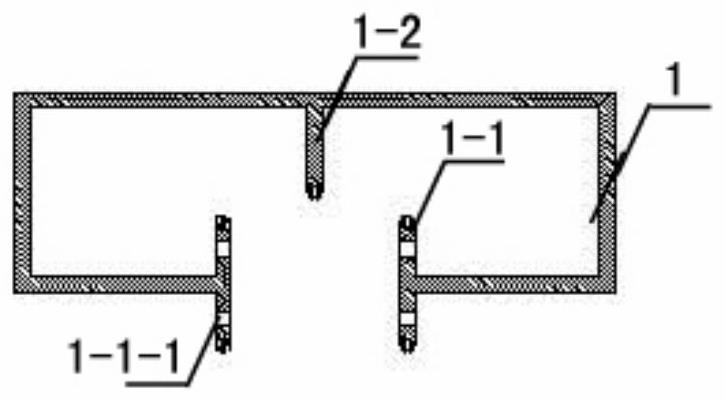
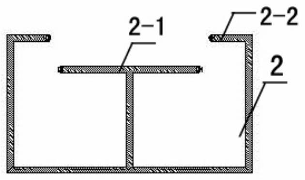
[0032] refer to Figure 1-Figure 6 , the anti-shock energy dissipation limit device for high-energy tubes involved in this embodiment is composed of anti-swing energy dissipation and position-limiting annular restraints, and the annular restraints include an inner ring cylinder 1 and an outer ring Cylinder 2, a built-in annular cylinder 3 is embedded in the outer ring cylinder 2; the inner ring cylinder 1 is sleeved on the high-energy tube 10, the outer ring cylinder 2 forms a fixed cylinder for the external fixed connection end, and the inner ring cylinder 1 The ring cylinder 1 is integrated with the outer ring cylinder 2 through the built-in ring cylinder 3 to form a radial limit structure; The cylinder body 3 and the outer ring cylinder body 2 form an embedding movable connection structure, and the built-in ring cylinder body 3 and the inner ring cylinder body 1 are movable cylinder bodies, forming a multi-directional rotation and longitudinal limit structure; the inner rin...

specific Embodiment

[0064] The characteristics of other specific embodiments of the present invention are: the inclination angle α depends on the characteristics of the load, and can be any angle outside the range of 0-30°, for example: it can be 1°, 5°, 10°, 17° °, 20°, 25° or 30°. All the other are with specific embodiment 1.

[0065] In summary, the present invention refers to the following principles when designing the anti-slam restraint: (1) in the running and anti-snap stages, it has the recovery ability to return to the original position after the vibration is terminated; (2) it has certain damping (3) Good durability, stable performance, no large changes in elasticity or other physical and chemical properties due to changes in external temperature, humidity and other conditions; (4) Convenient and economical materials Practical; (5) On the premise of meeting the bearing capacity and other performance requirements, the cost should be reduced as much as possible. The invention is to prev...


PUM


Abstract

The invention relates to an anti-whipping energy dissipation limiting device for a high-energy pipe. The anti-whipping energy dissipation limiting device is characterized in that the device is composed of an anti-whipping energy dissipation and limiting annular restraining piece, the annular restraining piece comprises an inner ring cylinder body and an outer ring cylinder body, and a built-in annular cylinder body is embedded into the outer ring cylinder body; a high-energy pipe is sleeved with the inner ring cylinder body, the outer ring cylinder body is an external fixed connecting end to form a fixed cylinder body, and the inner ring cylinder body and the outer ring cylinder body are connected into a whole through the built-in annular cylinder body to form a radial limiting structure; the inner ring cylinder body and the built-in annular cylinder body form a nested movable connection structure, the built-in annular cylinder body and the outer ring cylinder body form a nested movable connection structure, and the built-in annular cylinder body and the inner ring cylinder body are movable cylinder bodies and form a multi-directional rotation and longitudinal limiting structure; and elastic buffer units are arranged at the gap position of the joint of the inner ring cylinder body and the built-in annular cylinder body and the gap position of the joint of the outer ring cylinder body and the built-in annular cylinder body to form a built-in damping and energy dissipation structure. The device has the advantages of preventing the fixed end and the pipeline from being damaged and the like.

Description

technical field [0001] The invention relates to a swing-proof and energy-dissipating limiting device for high-energy tubes, which is suitable for high-energy tube swing-proof and energy dissipation in nuclear power plants, thermal power plants, cogeneration projects and heating equipment. It belongs to the field of electric equipment and application technology. Background technique [0002] At present, high-energy pipelines are widely used in the field of electric power and heating, such as nuclear power plants, thermal power plants, combined heat and power projects, and heating stations. The high-temperature and high-pressure steam in this type of pipeline contains huge energy. Once the pipeline breaks, the phenomenon of pipeline jetting and pipe throwing may cause considerable loss of personnel and economy. [0003] As one of the clean energy in power generation field, nuclear power is widely used. In nuclear power plants, slam-resistant structures are often used as a tr...

Claims


Application Information

Patent Timeline
IPC IPC(8): F16L55/02F16L55/033F16F15/02F16F15/023F16F15/067
CPCF16L55/02F16L55/033F16L55/005F16F15/022F16F15/023F16F15/067F16F2238/026
Inventor 陈康华
Owner CHINA ENERGY ENG GRP GUANGDONG ELECTRIC POWER DESIGN INST CO LTD
Why Eureka
Try Eureka